Supercharge Your Innovation With Domain-Expert AI Agents!

Rotor assembly and winding process thereof

A technology of rotor windings and components, which is applied in the direction of electric components, windings, electrical components, etc., and can solve problems such as broken rotor windings, paint wear, and short circuits

Inactive Publication Date: 2021-02-19
东风博泽汽车系统有限公司
View PDF2 Cites 0 Cited by
  • Summary
  • Abstract
  • Description
  • Claims
  • Application Information

AI Technical Summary

Problems solved by technology

[0003] figure 1 It is a schematic diagram of the structure of the existing rotor assembly. The use of the existing winding method will cause the rotor winding to generate stress crossing in the suspended part. Without any support, the tension of the winding cannot be removed.
Therefore, the high-frequency vibration may wear the paint and cause a short circuit, or the rotor winding may be strangled due to the mutual stress of the cross wires.

Method used


Image

  • Rotor assembly and winding process thereof
  • Rotor assembly and winding process thereof
  • Rotor assembly and winding process thereof

Examples


Embodiment Construction

[0031] The principles and features of the present invention are described below in conjunction with the accompanying drawings, and the examples given are only used to explain the present invention, and are not intended to limit the scope of the present invention.

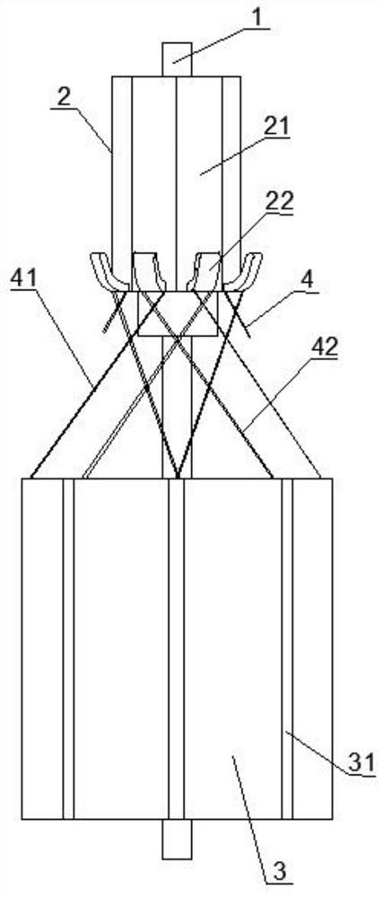
[0032] figure 1 It is a structural schematic diagram of an existing rotor assembly, including a rotating shaft 1 , a commutator 2 and an iron core 3 arranged on the rotating shaft 1 . The rotor winding 4 is directly wound between the commutator 2 and the iron core 3 . The rotor winding 4 includes an outgoing wire 41 drawn from the commutator 2 to the iron core 3 and a return wire 42 drawn from the iron core 3 to the commutator 2 . It can be seen from the figure that the rotor winding 4 has a large number of intersections in the suspension. Since the outlet wire 41 and the return wire 42 do not have any support at the intersection, the tension of the rotor winding 4 cannot be released, so the high-speed vibration o...


PUM


Abstract

The invention relates to a rotor assembly, which comprises a rotating shaft, an iron core, a commutator and a rotor winding. The commutator and the iron core are arranged on the rotating shaft; the commutator comprises a plurality of commutator segments arranged around the circumference of the rotating shaft, and one end, close to the iron core, of each commutator segment is connected with a hook;the iron core is provided with a plurality of rotor grooves arranged around the circumference of the rotating shaft, and the rotor grooves are in one-to-one correspondence with the commutator segments; one end of the rotor winding is wound in the rotor groove, and the other end is hung on the hook; the rotor winding comprises an outgoing line led out from the hook to the rotor groove and a returnline led out from the rotor groove to the hook, and the outgoing line and the return line are tightly attached to and wound on the rotating shaft; according to the invention, the rotor winding is wound on the rotating shaft, and the outgoing line and the return line are respectively arranged in parallel, so that the outgoing line and the return line are crossed and clung to the rotating shaft, the crossing angle of the outgoing line and the return line is extremely small, the stress between the connecting lines is transferred to the rotating shaft, and the rotor winding cannot be snapped offdue to stress crossing; and the rotor winding cannot be abraded due to high-frequency vibration.

Description

technical field [0001] The invention relates to the technical field of motor rotors, in particular to a rotor assembly and a winding process thereof. Background technique [0002] The rotor assembly of the existing window regulator motor for trucks is mainly composed of a rotating shaft, a rotor iron core, a rotor winding and a commutator. The rotor core and the commutator are arranged on the rotating shaft. The above-mentioned commutator is a hook-shaped commutator, which means that one end of the commutator segment of the commutator is provided with a hook. When the hook-shaped commutator winds the rotor winding, the wire ends of the winding are wound on the hooks of the commutator segments of the commutator. [0003] figure 1 It is a structural schematic diagram of the existing rotor assembly. The use of the existing winding method will cause the rotor winding to generate stress crossing in the suspended part, without any support, and the tension of the winding cannot ...

Claims


Application Information

Patent Timeline
Patent Type & Authority Applications(China)
IPC IPC(8): H02K3/28H02K3/46H02K13/04H02K15/09
CPCH02K3/28H02K3/46H02K13/04H02K15/09
Inventor 杨明邱秀敏黄伟吴昶
Owner 东风博泽汽车系统有限公司
Features
  • R&D
  • Intellectual Property
  • Life Sciences
  • Materials
  • Tech Scout
  • Unparalleled Data Quality
  • Higher Quality Content
  • 60% Fewer Hallucinations
Learn More