Soybean twisting piece processing equipment
A chip processing and soybean technology, which is applied in the field of soybean twist processing equipment, can solve the problems of not being able to crush multiple chips, not automatically collect, and consume energy, and achieve the effect of reducing the operation of manual collection
- Summary
- Abstract
- Description
- Claims
- Application Information
AI Technical Summary
Problems solved by technology
Method used
Image
Examples
Embodiment 1
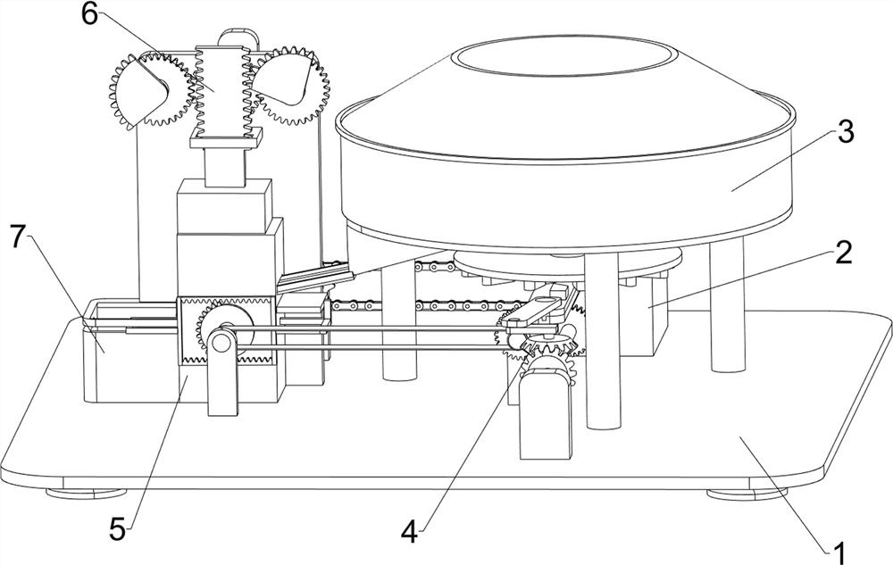
[0025]A processing equipment for twisting soybeans, such asfigure 1 As shown, it includes a base 1, a deceleration motor 2, a distributing mechanism 3, a transmission mechanism 4, and a hammer mechanism 6. A deceleration motor 2 is installed on the right side of the rear of the base 1, and a distributing mechanism is provided on the right side of the base 1. The material mechanism 3 is provided with a transmission mechanism 4 on the right side of the base 1, and the transmission mechanism 4 cooperates with the distributing mechanism 3, and a punch mechanism 6 is provided in the middle of the left side of the base 1, and the punch mechanism 6 is connected with the transmission mechanism 4.
[0026]First, people pour the soybeans to be stamped into the distributing mechanism 3, and then start the reduction motor 2, the output shaft of the reduction motor 2 drives the transmission mechanism 4 to drive, and the operation of the transmission mechanism 4 drives the distributing mechanism 3 t...
Embodiment 2
[0028]On the basis of Example 1, such asfigure 2 ,image 3 withFigure 4 As shown, the distributing mechanism 3 includes a first support column 31, a distributing tray 32, a first rotating shaft 33, a distributing sieve tray 34, a distributing baffle 35, a top cover 36 and a guide plate 37, on the base 1 Three first support columns 31 are evenly arranged on the right side. A distribution tray 32 is arranged between the tops of the first support columns 31. The center of the distribution tray 32 is rotatably provided with a first rotating shaft 33, and the upper part of the first rotating shaft 33 is provided with a distribution tray. The sieve tray 34 is provided with a top cover 36 on the top of the distributing tray 32. A distributing baffle 35 is provided between the top cover 36 and the first rotating shaft 33. The distributing baffle 35 is rotatably connected with the first rotating shaft 33. The distributing tray A material guide plate 37 is connected between 32 and the hammer m...
Embodiment 3
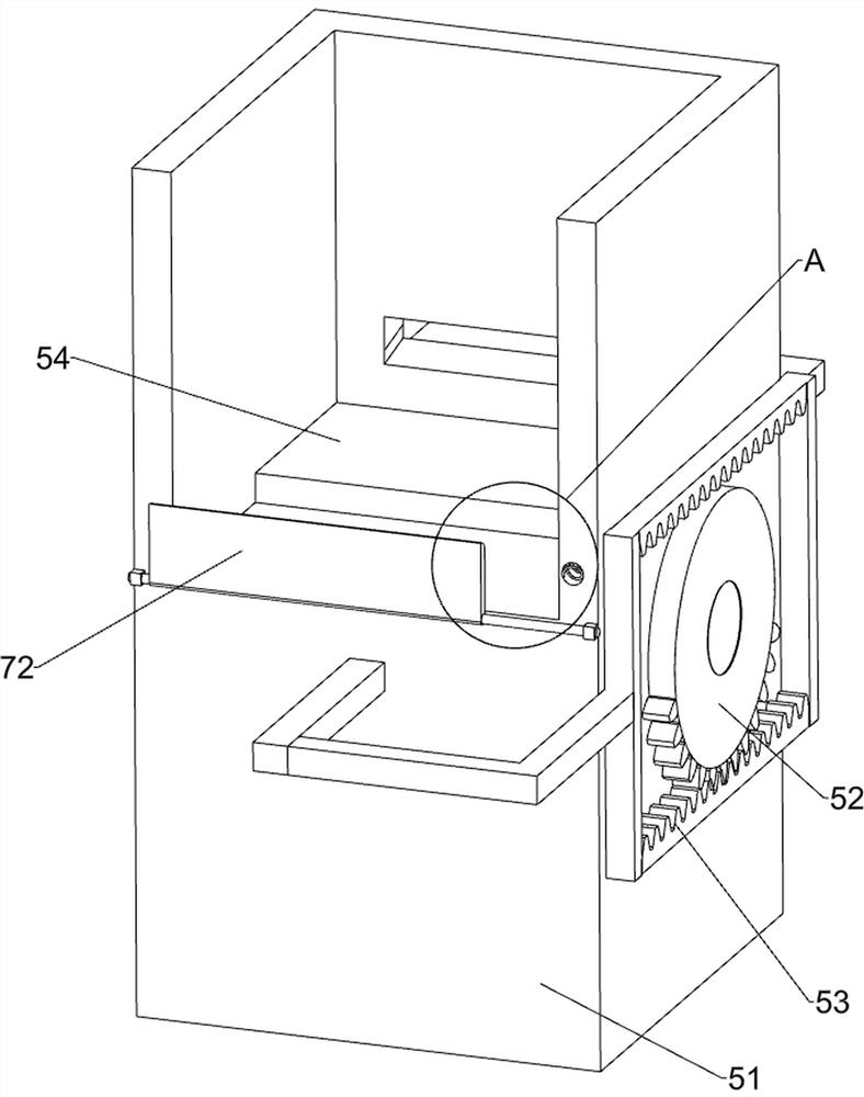
[0035]On the basis of Example 2, such asFigure 4 ,Figure 5 withFigure 6As shown, it also includes a pushing mechanism 5. The base 1 is provided with a pushing mechanism 5 on the left side of the front part. The pushing mechanism 5 is connected to the third rotating shaft 413. The pushing mechanism 5 includes a first missing gear 52, an inner The tooth frame 53 and the push plate 54 are provided with a first missing gear 52 on the rear side of the third rotating shaft 413 at the front left side, a push plate 54 is slidably provided in the middle of the stamping base 51, and an internal tooth frame 53 is provided on the front side of the push plate 54 , The inner gear frame 53 meshes with the first missing gear 52.
[0036]The rotation of the third shaft 413 on the front left side drives the rotation of the first missing gear 52. The first missing gear 52 engages with the lower part of the inner tooth frame 53 to drive the inner tooth frame 53 to move to the right, so that the push plate...
PUM
 Abstract
Description
Claims
Application Information
 - R&D
- Intellectual Property
- Life Sciences
- Materials
- Tech Scout
- Unparalleled Data Quality
- Higher Quality Content
- 60% Fewer Hallucinations
Browse by: Latest US Patents, China's latest patents, Technical Efficacy Thesaurus, Application Domain, Technology Topic, Popular Technical Reports.
© 2025 PatSnap. All rights reserved.Legal|Privacy policy|Modern Slavery Act Transparency Statement|Sitemap|About US| Contact US: help@patsnap.com


