Fructus aurantii cutting device for traditional Chinese medicine processing
A technology of citrus aurantium and traditional Chinese medicine, which is applied in the field of citrus aurantium cutting device for processing traditional Chinese medicine, which can solve the problems of easy injury of slicing, great effort, and slow slicing efficiency, and achieve the effect of easy falling
- Summary
- Abstract
- Description
- Claims
- Application Information
AI Technical Summary
Problems solved by technology
Method used
Image
Examples
Embodiment 1
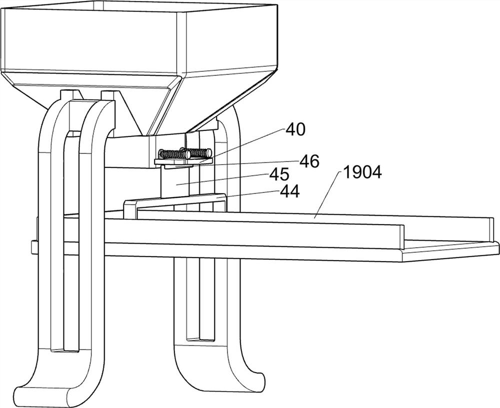
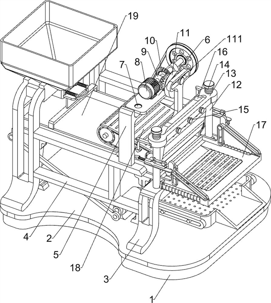
[0029] Such as figure 1 As shown, a Fructus Fructus Fructus cutting device for Chinese medicine processing includes a base 1, a bottom plate 2, a first support plate 3, a support frame 4, a second support plate 5, a mounting plate 6, a first fixing screw 7, a servo motor 8. The first bearing seat 9, the bevel gear assembly 10, the cam 11, the first fixed shaft 111, the first guide rod 12, the splint 13, the first spring 14, the second fixing screw 15, the slicing knife 16, the guard plate 17, The extruding mechanism 18 and the feeding mechanism 19, the base 1 is provided with a base plate 2, the left side of the base plate 2 is symmetrically provided with a first support plate 3, and the right side of the base plate 2 is provided with a first support plate 3. A support frame 4 is arranged symmetrically front and back between the first support plates 3 on the left and right sides, a second support plate 5 is arranged on the support frame 4 on the front side, and a mounting plat...
Embodiment 2
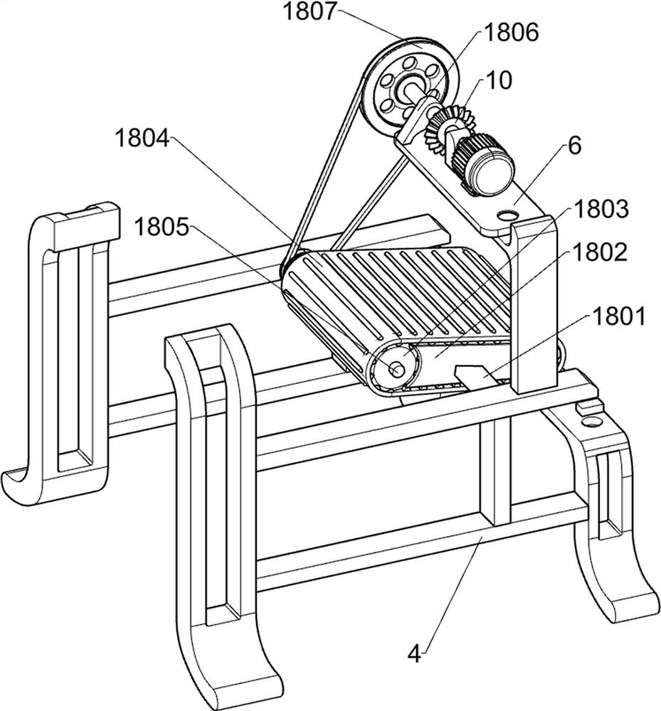
[0032] Such as figure 2 and image 3 As shown, on the basis of Embodiment 1, the extrusion mechanism 18 includes a connecting rod 1801, a first connecting block 1802, a hub 1803, a pressure belt 1804, a first rotating shaft 1805, a second bearing seat 1806 and a first pulley assembly 1807, connecting rods 1801 are provided on opposite sides of the two supporting frames 4, and a first connecting block 1802 is arranged between the two connecting rods 1801, and the left and right sides of the first connecting block 1802 are rotatably arranged There is a first rotating shaft 1805, hubs 1803 are arranged at the front and rear ends of the two first rotating shafts 1805, pressure belts 1804 are arranged between the four hubs 1803, and a second bearing seat 1806 is arranged on the mounting plate 6 A first pulley assembly 1807 is arranged between the output shaft of the servo motor 8 and the rear end of the first rotating shaft 1805 on the left side. The first pulley assembly 1807 is...
Embodiment 3
[0037] Such as Figure 4 , Figure 5 , Figure 6 , Figure 7 and Figure 8 As shown, on the basis of Embodiment 2, it also includes a first chute plate 20, a sliding shaft 21, a pressing plate 22, a push block 23, a second connecting rod 24, a pressing block 25, a fixing block 26, a second guide Rod 27, second spring 28, lever 29, the sixth connecting shaft 291, torsion spring 292, the third guide rod 293, the third spring 294, the first wedge block 295, the second connecting block 30, the third connecting rod 301 and The second wedge-shaped block 302, the first chute plate 20 is provided on the front and rear sides of the right part of the guard plate 17, and the two first chute plates 20 are slidably provided with a sliding shaft 21, and the two first chute plates 20 are slidably provided with a sliding shaft 21. The opposite ends of the sliding shafts 21 are provided with a pressure plate 22, and a push block 23 is arranged between the opposite ends of the two sliding s...
PUM
 Abstract
Description
Claims
Application Information
 - R&D
- Intellectual Property
- Life Sciences
- Materials
- Tech Scout
- Unparalleled Data Quality
- Higher Quality Content
- 60% Fewer Hallucinations
Browse by: Latest US Patents, China's latest patents, Technical Efficacy Thesaurus, Application Domain, Technology Topic, Popular Technical Reports.
© 2025 PatSnap. All rights reserved.Legal|Privacy policy|Modern Slavery Act Transparency Statement|Sitemap|About US| Contact US: help@patsnap.com


