Steel pipe punching device for building construction

A technology of building construction and punching device, which is applied in the field of building construction, and can solve problems such as cumbersome operation steps, affecting normal installation, and low punching efficiency

Inactive Publication Date: 2021-02-23
潘帅
View PDF0 Cites 5 Cited by
  • Summary
  • Abstract
  • Description
  • Claims
  • Application Information

AI Technical Summary

Problems solved by technology

This kind of punching operation method requires the use of clamps to fix the steel pipe before punching the steel pipe, and then punches the hole. After the punching is completed, the clamp is opened, and the steel pipe is rotated at a certain angle before p

Method used


Image

  • Steel pipe punching device for building construction
  • Steel pipe punching device for building construction
  • Steel pipe punching device for building construction

Examples


Embodiment 1

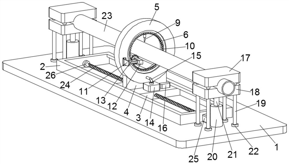
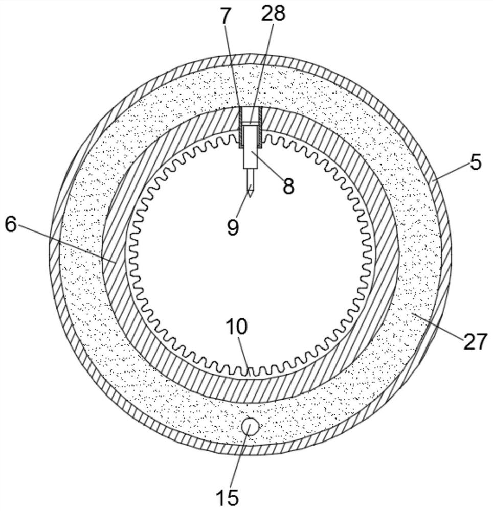
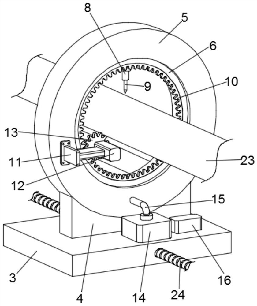
[0025] see Figure 1-2 , a steel pipe punching device for building construction, including a base 1, a slide rail 2 is installed on the base 1, a slide block 3 is slidably embedded in the slide rail 2, and the upper end of the slide block 3 passes through a support plate 4 A ring sleeve 5 is fixedly installed, and an annular cavity 27 is provided in the ring sleeve 5. A rotating ring 6 is fixedly mounted on the inner side of the ring sleeve 5, and a ring communicating with the annular cavity 27 is fixedly installed on the rotating ring 6. Sleeve 7, a telescopic ejector rod 8 is set movable in the sleeve 7, and a push plate 28 is fixed at one end of the telescopic ejector rod 8 toward the inside of the sleeve 7, and a punch is installed at the extended end of the telescopic ejector rod 8 head 9, a hydraulic device 14 is installed on the slider 3, and a hydraulic pipe 15 is communicated between the hydraulic device 14 and the annular cavity 27;

[0026] see image 3 A rotating...

Embodiment 2

[0039]A steel pipe punching device for building construction, comprising a base 1, on which a slide rail 2 is installed, and a slide block 3 is slidably embedded in the slide rail 2, and the upper end of the slide block 3 is fixed by a support plate 4 A ring sleeve 5 is installed, and an annular cavity 27 is provided in the ring sleeve 5. A rotating ring 6 is fixedly mounted on the inner side of the ring sleeve 5, and a sleeve communicating with the annular cavity 27 is fixedly installed on the rotating ring 6. Sleeve 7, the movable sleeve of the sleeve 7 is equipped with a telescopic ejector rod 8, the end of the telescopic ejector rod 8 facing the sleeve 7 is fixed with a push plate 28, and the extended end of the telescopic ejector rod 8 is equipped with a punch 9. A hydraulic device 14 is installed on the slider 3, and a hydraulic pipe 15 is communicated between the hydraulic device 14 and the annular cavity 27;

[0040] A rotating motor 12 is fixedly installed on the oute...


PUM


Abstract

The invention discloses a steel pipe punching device for building construction. The steel pipe punching device comprises a base, a sliding rail is installed on the base, a ring sleeve is installed inthe sliding rail in a sliding mode, an annular cavity is formed in the ring sleeve, a rotating ring is rotationally clamped on the inner side of the ring sleeve, a sleeve is fixedly installed on the rotating ring, a telescopic ejector rod is movably sleeved with the sleeve, a punch is installed at the extending tail end of the telescopic ejector rod, and a hydraulic device communicating with the annular cavity is installed on a sliding block; a rotating motor is installed on the outer wall of the ring sleeve, a gear is rotationally installed at the output end of the rotating motor, a gear ringis arranged on the inner wall of the rotating ring, and a controller is installed on the sliding block; and a transverse moving mechanism is arranged on the sliding rail, and clamping assemblies arearranged at the two ends of the sliding rail. According to the steel pipe punching device for building construction, a steel pipe is clamped and fixed through the clamping assemblies, the ring sleeveis driven by the transverse moving mechanism to move transversely along the steel pipe, and meanwhile, the punch can rotate around the circumferential direction of the steel pipe to any angle, and therefore punching operation of the steel pipe at different positions and angles is achieved, adjustment is convenient and flexible, the punching precision is high, and the punching efficiency is improved.

Description

technical field [0001] The invention relates to the technical field of building construction, in particular to a steel pipe punching device for building construction. Background technique [0002] During the building construction process, it is often necessary to punch holes in the steel pipes, so as to facilitate the subsequent installation of the steel pipes. At present, steel pipes are generally punched by first fixing the steel pipes, punching holes with a punching punch, then rotating the steel pipes to the position that needs to be punched, and then performing fixed punching. This kind of punching operation method requires the use of clamps to fix the steel pipe before punching the steel pipe, and then punches the hole. After the punching is completed, the clamp is opened, and the steel pipe is rotated at a certain angle before punching again. The operation steps are cumbersome and the punching efficiency is low. Moreover, the accuracy of circumferential punching cann...

Claims


Application Information

Patent Timeline
IPC IPC(8): B21D28/28B21D28/36
CPCB21D28/28B21D28/36
Inventor 潘帅
Owner 潘帅
Why Eureka
Try Eureka