

Lifting mechanism of electroplating equipment
A lifting mechanism and electroplating equipment technology, applied in the direction of cranes, electrolysis process, electrolysis components, etc., can solve the problem of low practicability of the lifting mechanism, and achieve the effect of high practicability, easy installation and use
Pending Publication Date: 2021-02-23
汤润枚
View PDF4 Cites 1 Cited by
- Summary
- Abstract
- Description
- Claims
- Application Information
AI Technical Summary
Problems solved by technology
[0003] The purpose of the present invention is to provide a lifting mechanism for electroplating equipment, which has the advantage of high practicability and solves the problem of low practicability of the lifting mechanism for existing electroplating equipment
Method used
View moreImage
Smart ImageViewing Examples

Examples
Embodiment Construction
[0017] The following will clearly and completely describe the technical solutions in the embodiments of the present invention with reference to the accompanying drawings in the embodiments of the present invention. Obviously, the described embodiments are only some, not all, embodiments of the present invention. Based on the embodiments of the present invention, all other embodiments obtained by persons of ordinary skill in the art without making creative efforts belong to the protection scope of the present invention.
Login to View More PUM
 Abstract
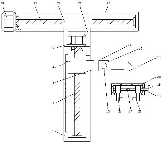
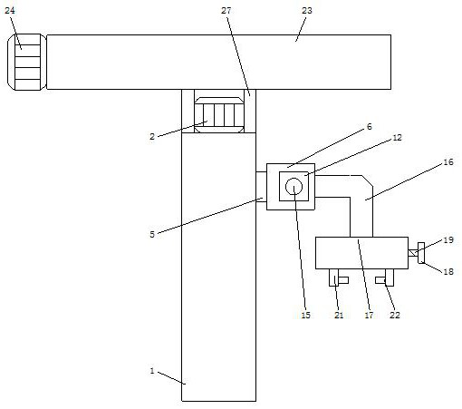
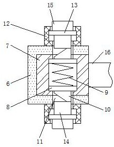
The invention discloses a lifting mechanism of electroplating equipment. The lifting mechanism comprises an adjusting base, wherein a first motor is fixedly connected to the top of the adjusting base,a first threaded rod is fixedly connected to the bottom of the output end of the first motor, and the bottom of the first threaded rod penetrates through the bottom of an inner cavity of the adjusting base and is sleeved with a first threaded sleeve; and the right side of the first threaded sleeve is fixedly connected with a connecting block, and the right side of the connecting block penetratesinto the right side of the adjusting base and is fixedly connected with a mounting shell. By arranging the adjusting base, the first motor, the first threaded rod, the first threaded sleeve, the connecting block, the mounting shell, a mounting block, push plates, a spring, clamping blocks, inserting holes, limiting boxes, pressing plates, pressing blocks, push blocks, a connecting frame, a limiting shell, a hand wheel, a second threaded rod, second threaded sleeves, adjusting frames and clamping blocks, the problem that an existing lifting mechanism of the electroplating equipment is low in practicability is solved; and the lifting mechanism of the electroplating equipment has the beneficial effect of being high in practicability and worthy of popularization.
Description
technical field [0001] The invention relates to the technical field of electroplating equipment, in particular to an electroplating equipment lifting mechanism. Background technique [0002] Electroplating is the process of plating a layer of other metals or alloys on the surface of certain metals using the principle of electrolysis. It is a process of using electrolysis to attach a layer of metal film to the surface of metal or other material parts, so as to prevent metal oxidation and improve Wear resistance, electrical conductivity, reflectivity, corrosion resistance, and aesthetic enhancement. The current VCP electroplating equipment mainly relies on manual control of the lifting of the workpiece, which is low in efficiency, high in labor costs, and inconvenient to assemble and disassemble. It is convenient to fix workpieces of different specifications, which reduces the practicability of the lifting mechanism of the electroplating equipment and is not conducive to use. ...
Claims
Login to View More Application Information
Patent Timeline
 Patent Type & AuthorityApplications(China)
IPC IPC(8): B66C1/44B66C25/00C25D17/00
CPCB66C1/44B66C25/00C25D17/00
Inventor汤润枚
Owner汤润枚