Sponge city water storage pipeline anti-blocking structure

A sponge city, anti-clogging technology, applied in the sewer system, waterway system, general water supply conservation, etc., can solve the problems of self-cleaning, anti-blocking detection and cleaning, and automatic cleaning of silt, etc. Achieve the effect of reducing the possibility of clogging and rapid flushing

Active Publication Date: 2021-02-23
青岛市城市规划设计研究院
View PDF8 Cites 6 Cited by
  • Summary
  • Abstract
  • Description
  • Claims
  • Application Information

AI Technical Summary

Problems solved by technology

[0003] Among them, the application number is CN201911213012.1, a sponge city rainwater decontamination, diversion and anti-blocking device, which can divert the rainwater by setting the drainage main pipe and the shunt pipe; slow down the pressure of the main pipe during drainage, and prevent the pipe from bursting when the flow rate is too large , and the drainage flow of the drainage main pipe can be detected by the detection device. When the drainage flow increases or the outlet flow decreases, the water flow increases or the filter screen is blocked, that is, the water flow is controlled to enter the shunt pipe. The filter screen anti-blocking device is driven by the water flow in the shunt pipe to clean the blocked filter screen in the main drainage pipe, but the anti-blocking structure described in this technical solution uses electric drive and detection to realize the anti-blocking cleaning of the filter screen. Once the power is disconnected, this technical solution cannot realize the detection and cleaning of the anti-blocking, and it is easy to occur that the silt cannot be automatically cleaned. In particular, once the silt is blocked inside the anti-blocking structure, the device itself cannot self-cleaning

Method used


Image

  • Sponge city water storage pipeline anti-blocking structure
  • Sponge city water storage pipeline anti-blocking structure
  • Sponge city water storage pipeline anti-blocking structure

Examples


Embodiment Construction

[0023] The following will clearly and completely describe the technical solutions in the embodiments of the present invention with reference to the accompanying drawings in the embodiments of the present invention. Obviously, the described embodiments are only some, not all, embodiments of the present invention. Based on the embodiments of the present invention, all other embodiments obtained by persons of ordinary skill in the art without making creative efforts belong to the protection scope of the present invention.

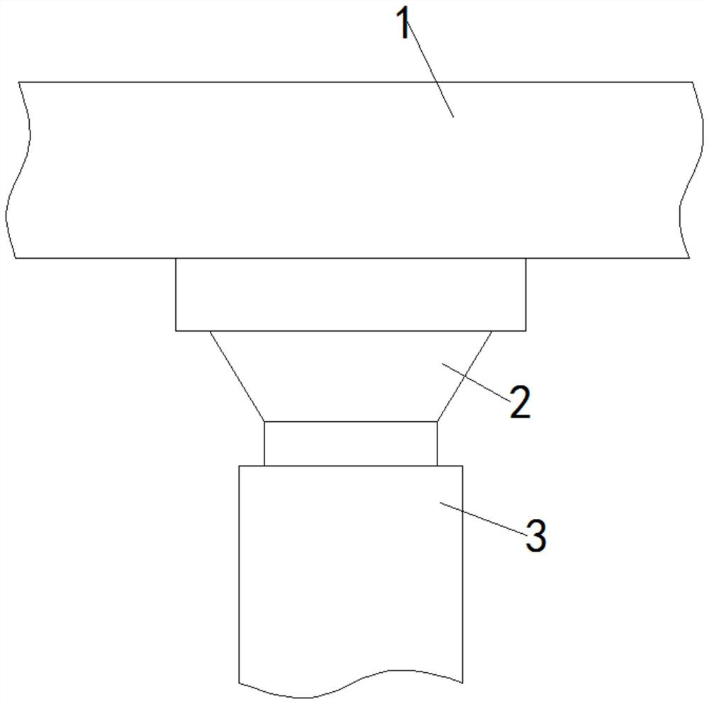
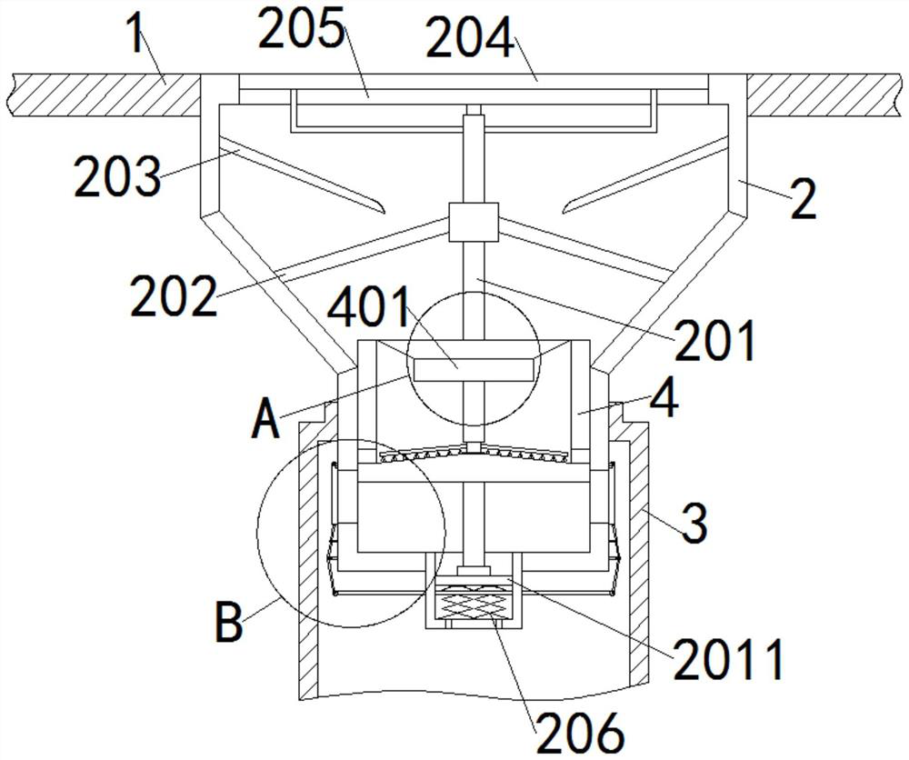
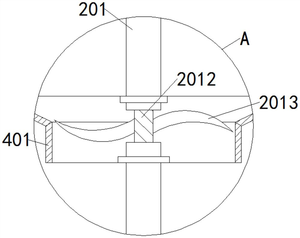
[0024] see Figure 1-6 , in an embodiment of the present invention, an anti-clogging structure of a sponge city water storage pipeline, including a water delivery pipe 1, a dredging pipeline 2, a central axis rod 201, a bottom plate 2011, a rotating rod 2012, a water wheel blade 2013, a support L rod 2014, a cleaning Rod 2015, bristles 2016, fixed rod 202, guide plate 203, filter layer 204, grille layer 205, telescopic spring 206, water outlet 207, transverse ...


PUM


Abstract

The invention provides a sponge city water storage pipeline anti-blocking structure, and belongs to the technical field of pipeline drainage. The sponge city water storage pipeline anti-blocking structure comprises a water conveying pipe, a dredging pipeline is fixedly connected to the lower surface of the water conveying pipe, a distributary pipe is nested in the top of the dredging pipeline, aninner sliding sleeve is slidably connected into the dredging pipeline, and a middle shaft rod is rotatably connected into the dredging pipeline. According to the sponge city water storage pipeline anti-blocking structure, water wheel blades are arranged, water flow impacts the surfaces of the water wheel blades under the guidance of a guide plate through the gravity effect, the water wheel bladesrotate under the impact of the water flow and drive rotating rods to rotate, and the synchronous rotating rods rotate to drive cleaning rods to swing; and furthermore, bristles continuously brush thelower surface of a filter layer, the upper surface of a grid layer and the bottom end in the inner sliding sleeve, impurities at the three positions are removed, sludge is effectively prevented from being deposited at the filter layer and the bottom end in the inner sliding sleeve, and the clogging possibility of the device is greatly reduced.

Description

technical field [0001] The invention relates to the technical field of pipeline drainage, in particular to a pipeline anti-blocking structure. Background technique [0002] Sponge city is a new generation of urban stormwater management concept. It means that the city can be like a sponge, and has good elasticity in adapting to environmental changes and dealing with natural disasters caused by rainwater. It can also be called "water elastic city". The international general term is "low-impact development rainwater system construction", which absorbs, stores, infiltrates, purifies water when it rains, and releases and utilizes the stored water when needed, so as to realize the free migration of rainwater in the city and from the ecosystem. Starting from services, constructing water ecological infrastructure across scales and combining various types of specific technologies to build water ecological infrastructure is the core of the sponge city. [0003] Among them, the applic...

Claims


Application Information

Patent Timeline
Patent Type & Authority Applications(China)
IPC IPC(8): E03F1/00E03F3/04
CPCE03F1/002E03F3/04Y02A20/108
Inventor 梁志涌
Owner 青岛市城市规划设计研究院
Why Eureka
Try Eureka