Experimental device and method for detecting gas-phase fracturing working pressure and fracturing effect

A technology of working pressure and experimental equipment, which is applied in the directions of measurement, earthwork drilling, mining fluid, etc., can solve the problems of imperfect equipment and methods, large error of test results, heavy workload, etc., and achieve low cost of use and maintenance, and convenience Research and promote the application, use the effect of high safety

Pending Publication Date: 2021-02-23
HENAN POLYTECHNIC UNIV
View PDF2 Cites 2 Cited by
  • Summary
  • Abstract
  • Description
  • Claims
  • Application Information

AI Technical Summary

Problems solved by technology

The current test method mainly uses PCB and PVDF dynamic sensors to directly test the pressure of the jetted high-pressure gas. However, due to the high pressure and fast speed of the jetted gas, the test results have large errors, cumbersome process, and heavy workload, which cannot meet the requirements. Practical application needs
Especially when the gas-phase fracturing technology is applied in the process of fracturing and stimulating oil and gas wells, the working pressure alone is far from enough. It is also necessary to conduct experimental research on the law of gas-phase fracturing fracture propagation on reservoir samples. Existing experimental equipment and methods Not perfect, and there are many problems

Method used


Image

  • Experimental device and method for detecting gas-phase fracturing working pressure and fracturing effect
  • Experimental device and method for detecting gas-phase fracturing working pressure and fracturing effect
  • Experimental device and method for detecting gas-phase fracturing working pressure and fracturing effect

Examples


Embodiment Construction

[0027]In order to make the technical means, creative features, goals and effects achieved by the present invention easy to understand, the present invention will be further described below in conjunction with specific embodiments.

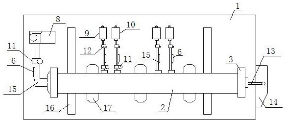
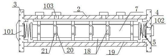
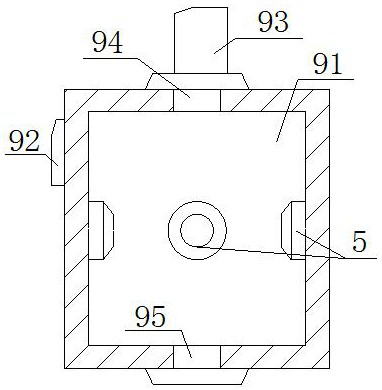
[0028] Such as Figure 1-4 As shown, an experimental device for detecting the working pressure and fracturing effect of gas-phase fracturing, including a bearing base 1, an experimental chamber 2, a sealing cover 3, a bearing spring 4, a mechanical pressure sensor 5, a fluid pressure sensor 6, a gas-phase fracturing Device 7 , booster pump 8 , pressure detection experiment chamber 9 , fracturing effect detection experiment chamber 10 , control valve 11 , pressure limiting valve 12 , control wire 13 and drive circuit 14 . The bearing base 1 is a frame structure with a rectangular cross section and the axis is parallel to the horizontal plane. The experimental cavity 2 is connected to the upper end surface of the bearing base 1 and distributed parall...


PUM


Abstract

The invention relates to an experimental device for detecting gas-phase fracturing working pressure and fracturing effect. The experimental device comprises a bearing base, an experimental cavity, sealing covers, a gas-phase fracturing device, a booster pump, a pressure detection experimental cavity, a fracturing effect detection experimental cavity and a control wire, the experimental cavity is connected with the upper end face of the bearing base, and the front end face and the rear end face of the experimental cavity are connected with the sealing covers; and a flow guide pipe communicateswith the booster pump through one sealing cover, the control wire is electrically connected with a driving circuit through one end of a wire inlet hole of the other sealing cover, the other end of thewire inlet hole is electrically connected with the gas phase fracturing device, and the experiment cavity communicates with the pressure detection experiment cavity and the fracturing effect detection experiment cavity through drainage ports. The using method comprises the three steps of equipment assembling, equipment prefabricating and fracturing experiments. According to the experimental device, on one hand, the working pressure detection of different types of gas phase fracturing equipment can be realized; and on the other hand, the actual blasting data of an air pressure fracturing blasting device is accurately detected, and meanwhile the development law of fracturing cracks under different reservoir conditions is obtained.

Description

technical field [0001] The invention relates to a gas phase fracturing simulation detection device, in particular to an experimental device and a detection method for detecting gas phase fracturing working pressure and fracturing effect. Background technique [0002] As a new type of blasting and fracturing technology, it has been widely used in coal mine safety production, oil and gas well fracturing stimulation, and surface mine blasting. The working principle of gas-phase fracturing technology is: filling liquid CO in gas-phase fracturing equipment 2 , the detonator ignites the built-in heater, liquid CO 2 It is converted into high-pressure gas within 20-40 ms. After the gas pressure reaches the control pressure of the equipment, it is quickly ejected to act on the target body, breaking the target body or causing new cracks in the target body to achieve the purpose of blasting and fracturing. Gas phase fracturing technology is a non-explosive, green and pollution-free, ...

Claims


Application Information

Patent Timeline
Patent Type & Authority Applications(China)
IPC IPC(8): E21B47/06E21B47/00E21B41/00E21B43/26
CPCE21B47/06E21B47/00E21B41/00E21B43/26
Inventor 石玢曹运兴张军胜田林张新生郭帅房张震鲜保安张洲刘高峰
Owner HENAN POLYTECHNIC UNIV
Why Eureka
Try Eureka