Synchronous grouting device arranged in shield body

A synchronous grouting and shield technology, applied in shaft equipment, shaft lining, tunnel lining, etc., can solve problems such as the gap between segment and tunnel stratum, and achieve the effect of protecting pipeline, avoiding impact and reducing installation space.

Pending Publication Date: 2021-02-23
ANHUI TONGDU FLOW TECH
View PDF6 Cites 0 Cited by
  • Summary
  • Abstract
  • Description
  • Claims
  • Application Information

AI Technical Summary

Problems solved by technology

[0004] Aiming at the deficiencies of the prior art, the present invention provides a synchronous grouting device placed in the shield body, capable of performing synchronous grouting on formations with high permeability and formations that have formed cavities, and filling the gap between segments and formations in time It solves the problem that there is a gap between the segment and the tunnel stratum due to the diameter of the excavation surface of the cutter head being larger than the outer diameter of the segment during the excavation of the shield machine

Method used


Image

  • Synchronous grouting device arranged in shield body
  • Synchronous grouting device arranged in shield body
  • Synchronous grouting device arranged in shield body

Examples


Embodiment Construction

[0024] The following will clearly and completely describe the technical solutions in the embodiments of the present invention with reference to the accompanying drawings in the embodiments of the present invention. Obviously, the described embodiments are only some, not all, embodiments of the present invention. Based on the embodiments of the present invention, all other embodiments obtained by persons of ordinary skill in the art without making creative efforts belong to the protection scope of the present invention.

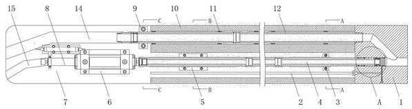
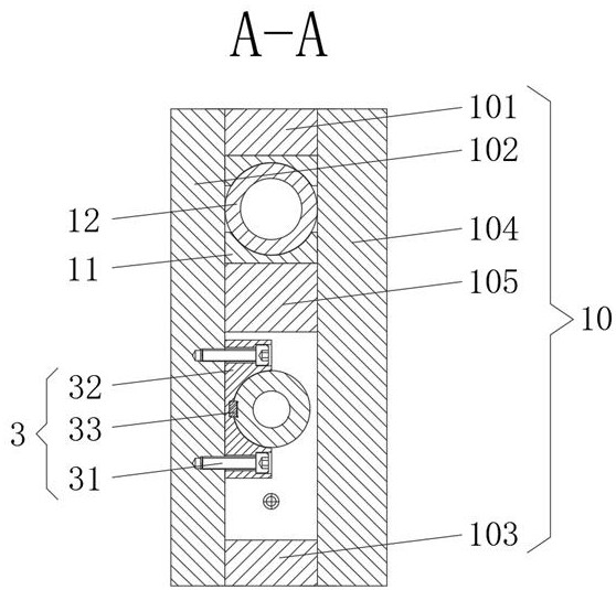
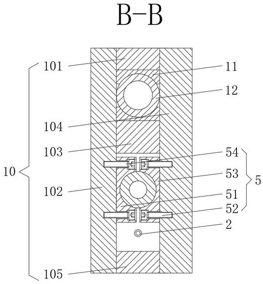
[0025] see Figure 1-7 , a synchronous grouting device placed in the shield body, including a grouting body 1, an upper baffle 7 and a protective cover 10, the grouting body 1 is located on the right side of the protective cover 10, and the upper baffle 7 is located on the left side of the protective cover 10 side, and the grouting body 1, the protective cover 10 and the upper baffle 7 are welded as a whole. In order to ensure that the protective cover 10 is w...


PUM


Abstract

The invention relates to the technical field of grouting, and discloses a synchronous grouting device arranged in a shield body. The synchronous grouting device comprises a grouting body, an upper baffle and a protective cover, a lubricating oil pipeline is arranged in the protective cover, a flushing pipe is arranged in the protective cover, and a guide device is arranged on the side surface of the flushing pipe; a flushing pipe pressing block is arranged on the side surface of the flushing pipe, a double-acting oil cylinder is fixedly installed on the front face of the upper baffle, a strokelimiting device is fixedly installed on the front face of the upper baffle, and a positioning stop block is fixedly installed on the front face of the upper baffle. According to the synchronous grouting device arranged in the shield body, the grouting body, the upper baffle, the protective cover, the lubricating oil pipeline, the flushing pipe and a mortar pipe are matched with one another, and the grouting body, a protective plate and the upper baffle are welded into a whole, so that the structure of the synchronous grouting device is firmer; and meanwhile, the lubricating oil pipeline, theflushing pipe and the mortar pipe are all arranged in the protective cover, impact of foreign objects is avoided, and the pipeline is protected.

Description

technical field [0001] The invention relates to the technical field of grouting, in particular to a synchronous grouting device placed in a shield body. Background technique [0002] At present, with a large number of tunnel constructions at home and abroad, shield machines have become the preferred equipment for excavation, and construction safety and surface settlement control are particularly important in construction; The outer diameter of the segments, which will lead to gaps between the segment and the tunnel formation, especially in some pebble formations, the pebbles are poor in self-stability and easily fall off; , due to the small content of fine particles, it is difficult to naturally form muck that can stop water, resulting in the instability of the excavation surface and the difficulty of controlling the surface settlement. Therefore, it is necessary to propose a synchronous grouting device placed in the shield body to solve the above problems question. Conte...

Claims


Application Information

Patent Timeline
IPC IPC(8): E21D9/06E21D11/10
CPCE21D9/0607E21D11/105
Inventor 李文东雷鹏王春陈磊巩文彬顾洪霞
Owner ANHUI TONGDU FLOW TECH
Why Eureka
Try Eureka