
Adjusting method for restraining inclination angle rotation errors of two-end supporting shafting structure

An assembly and adjustment method and a technology for supporting shafts, which are applied to rotating parts, shafts, and bearings that resist centrifugal force, can solve the problems of insufficient coaxial accuracy of bearing holes, difficult rotation accuracy, and incompleteness, etc., to reduce the dependence on assembly and adjustment experience , the steps are clear, and the effect of suppressing the inclination rotation error

Active Publication Date: 2021-02-23
TIANJIN JINHANG INST OF TECH PHYSICS
View PDF12 Cites 0 Cited by
  • Summary
  • Abstract
  • Description
  • Claims
  • Application Information

AI Technical Summary

Problems solved by technology

Patent CN 106624776 A discloses a shafting assembly method supported by a bidirectional single bearing with a certain span. This method improves the rotation accuracy of the shafting system by reasonably adjusting the preload of the bearing, and can adjust the rotation accuracy to 10″ However, if the coaxial accuracy of the bearing holes at both ends of the frame with a certain span is not enough, it will be difficult to further improve the rotation accuracy by this method
Patent CN 105387829 A discloses a method for adjusting the concentricity of the left and right half shafts of the turntable. The test index for installation and adjustment does not involve the inclination angle rotation error of the shaft system. The installation and adjustment method is to assemble the bearing on the right half shaft, fix the bearing seat, and measure the The shaft diameter jumps, and then adjust the left semi-axis to the allowable range. This method of adjustment is not perfect for the shaft system with high requirements on the inclination angle rotation error.

Method used


Image

  • Adjusting method for restraining inclination angle rotation errors of two-end supporting shafting structure
  • Adjusting method for restraining inclination angle rotation errors of two-end supporting shafting structure
  • Adjusting method for restraining inclination angle rotation errors of two-end supporting shafting structure

Examples


Embodiment Construction

[0027] In order to make the purpose, content, and advantages of the present invention clearer, the specific implementation manners of the present invention will be further described in detail below in conjunction with the accompanying drawings and embodiments.

[0028] The concept and test method of the inclination angle rotation error involved in the present invention can be found in GJB 1801 "Test Methods for Main Performance of Inertial Technology Test Equipment".

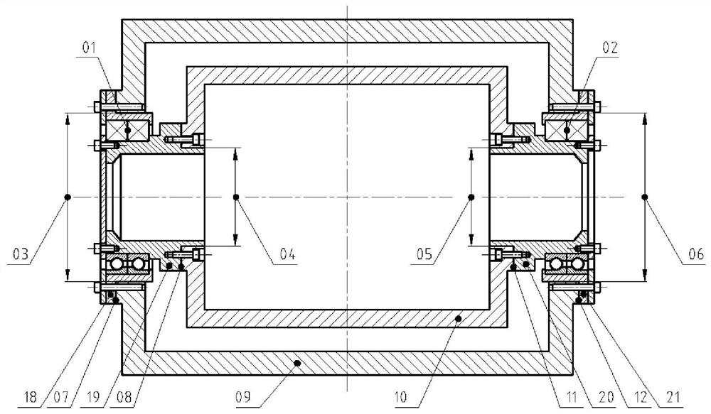
[0029] The model of a kind of two-end supporting shafting structure designed by the present invention is as follows: figure 1 As shown, the shafting structure is composed of four necessary parts: the left end bearing pair assembly 01, the right end bearing pair assembly 02, the outer frame 09 and the inner frame 10.

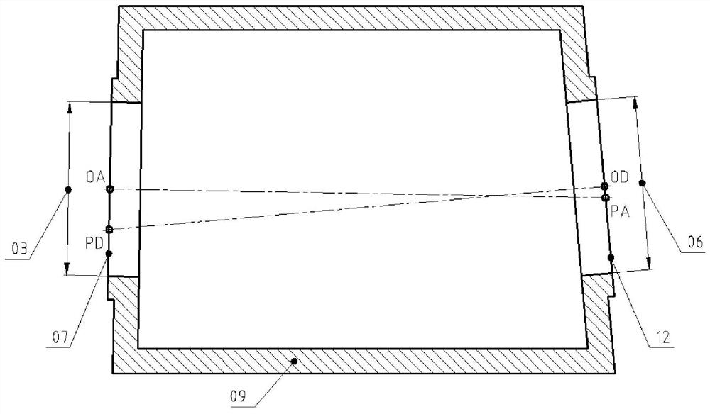
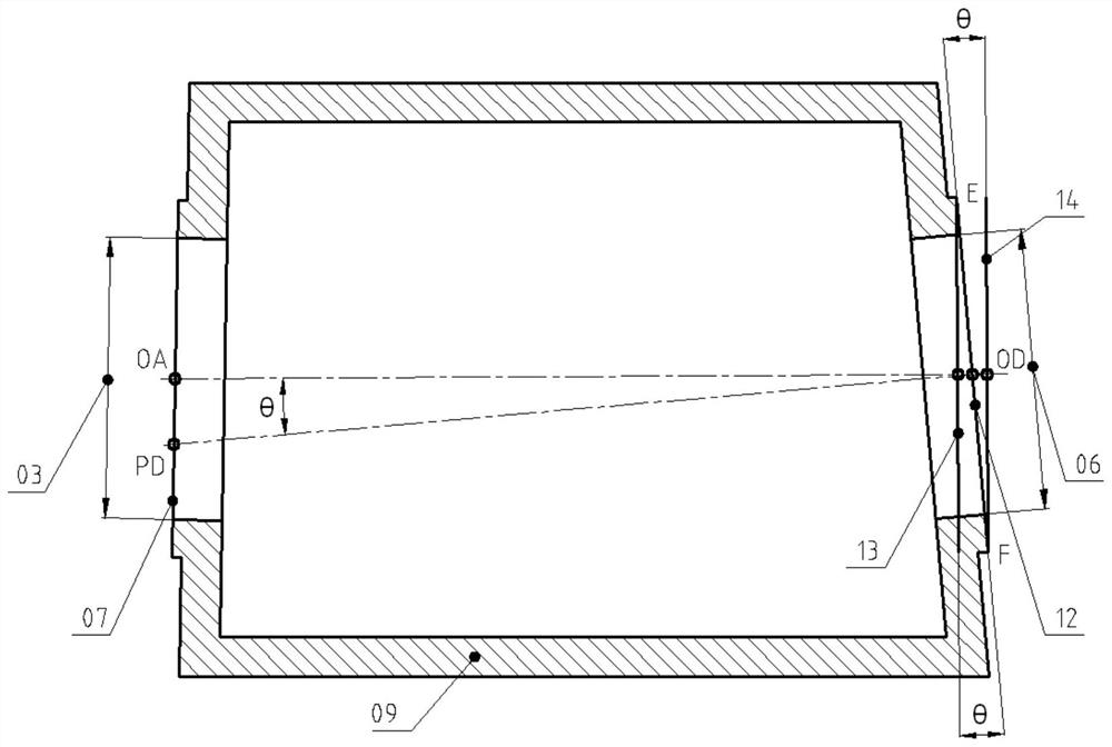
[0030] The left end bearing pair assembly 01 is composed of a left bearing seat 18, a left shaft 19 and a back-to-back bearing pair; the right end bearing pair assembly 02 is composed of a right be...


PUM


Abstract

The invention relates to an adjusting method for restraining inclination angle rotation errors of a two-end supporting shafting structure, and belongs to the technical field of precision shafting structure adjustment. According to the adjusting method, firstly, a model of the two-end supporting shafting structure is established, the adjusting method for restraining the inclination angle rotation errors of the two-end supporting shafting structure is introduced through the model, the steps are clear, dependence on the adjustment experience of operators is reduced, the method has the characteristic of completeness, assembling and machining errors can be effectively restrained by adopting the method to perform adjustment, and then the inclination angle rotation errors of the two-end supporting shafting system structure are effectively restrained.

Description

technical field [0001] The invention belongs to the technical field of assembly and adjustment of precision shafting structures, and in particular relates to an assembly and adjustment method for suppressing inclination rotation errors of shafting structures supported at both ends. Background technique [0002] At present, the assembly and adjustment of precision shafting structures is a core technology mastered by only a few units in China. It is an industry secret, and most of them are mastered by experienced technical experts. The quality of the assembly and adjustment is highly related to the experience value. . No patent has been retrieved for announcing an assembly method for suppressing the inclination rotation error of the supporting shafting structure at both ends. Check the patents related to the inclination rotation error, and find that most of them are related to the test method. For example, the patent CN 106352846 A provides a test method for the inclination r...

Claims


Application Information

Patent Timeline
Patent Type & Authority Applications(China)
IPC IPC(8): F16C25/06F16C23/06F16C35/06F16C35/067G01B5/00G01B5/14G01B5/24
CPCF16C25/06F16C23/06F16C35/061F16C35/067G01B5/24G01B5/00G01B5/14F16C2240/30
Inventor 王丰年霍国强李红沛崔佳李修斌祝世民
Owner TIANJIN JINHANG INST OF TECH PHYSICS
Learn More