
Display device

A display device and bar-shaped technology, which is applied in nonlinear optics, instruments, optics, etc., can solve the problems of increasing the number of lamp bead arrangement and reducing the distance between lamp bead

Pending Publication Date: 2021-02-23
HISENSE VISUAL TECH CO LTD
View PDF0 Cites 0 Cited by
  • Summary
  • Abstract
  • Description
  • Claims
  • Application Information

AI Technical Summary

Problems solved by technology

However, due to the requirements of the optical rigidity of the module, while reducing the number of light bars, it is still necessary to keep the total luminous flux unchanged, which results in an increase in the number of lamp beads arranged on a single light bar and a reduction in the distance between the light beads

Method used


Image

  • Display device
  • Display device
  • Display device

Examples


Embodiment Construction

[0035] In order to make the purpose, technical solutions and advantages of the present invention clearer, the present invention will be further described in detail below in conjunction with the accompanying drawings. Obviously, the described embodiments are only some of the embodiments of the present invention, rather than all of them. Based on the embodiments of the present invention, all other embodiments obtained by persons of ordinary skill in the art without making creative efforts belong to the protection scope of the present invention.

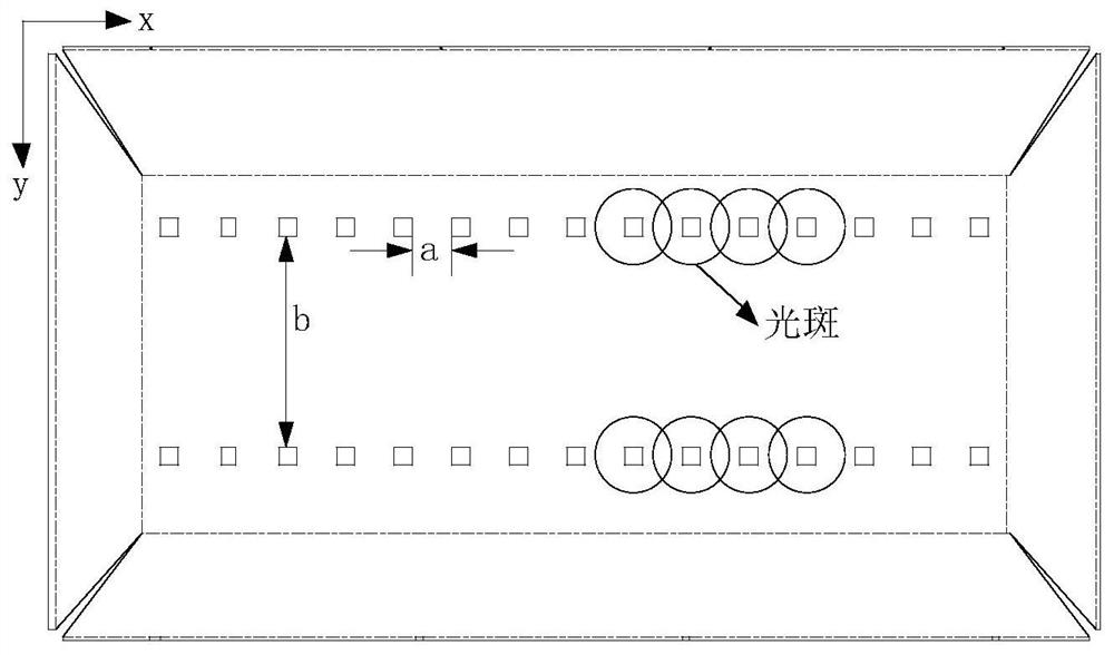
[0036] In order to reduce the production cost of the liquid crystal display device, it is necessary to reduce the number of light strips arranged on the backlight module, and while reducing the number of light strips, it is still necessary to keep the total luminous flux constant, which requires more than one light strip to be set on a single light strip. of light emitting devices. Such as figure 1 The shown top view structure of the b...


PUM


Abstract

The invention discloses a display device which comprises a light bar. The light bar comprises a strip-shaped circuit board and a plurality of light emitting devices positioned on the strip-shaped circuit board; the light-emitting devices are arranged in the extending direction of the strip-shaped circuit board; light emitted by the light-emitting devices forms light spots on the strip-shaped circuit board; and a plurality of mutually separated light absorption parts are arranged in the light spot areas on the two sides of the light-emitting devices in the extending direction of the strip-shaped circuit board, and the light absorption parts are used for absorbing incident light. The Light spots formed when the light-emitting devices irradiate the strip-shaped circuit board are overlapped, the light intensity in the area is large, the light absorption parts are arranged in the light spot areas on the two sides, in the extending direction of the strip-shaped circuit board, of the light-emitting devices, and therefore light in the area with the large light spot energy density can be properly absorbed; and therefore, light reflected to the side deviating from the strip-shaped circuit board is reduced, the emergent brightness of the light bar in the extending direction is uniform, and a bright band is prevented from being generated over the light bar.

Description

technical field [0001] The present invention relates to the field of display technology, in particular to a display device. Background technique [0002] The liquid crystal display panel is a non-self-illuminating display panel, and needs to cooperate with a backlight module to provide backlight to realize image display. Backlight modules are divided into direct-type backlight modules and side-type backlight modules according to their structural forms. Direct-lit backlight modules are widely used in LCD TVs due to their advantages such as good light-emitting viewing angle, high utilization rate, simple structure, and low cost. [0003] With the market competition of LCD TVs, the continuous cost optimization of low-end models has become the main trend of all modules. Measures such as eliminating silk screen printing on the diffusion plate and reducing the number of light bars have become design directions. However, due to the requirements of the optical rigidity of the mod...

Claims


Application Information

Patent Timeline
Patent Type & Authority Applications(China)
IPC IPC(8): G02F1/13357
CPCG02F1/133605G02F1/133606G02F1/133611
Inventor 张继兵闫高宾
Owner HISENSE VISUAL TECH CO LTD
Learn More