
Efficient textile dye mixing device for textile machinery

A technology for textile dyes and mixing devices, which is applied in mixers, mixers with rotating agitating devices, transportation and packaging, etc. It can solve the problems of ordinary and obsolete mixing methods, insufficient mixing range, and low mixing effect, and reach the mixing range Wide, stable stirring process, high degree of freedom effect

Inactive Publication Date: 2021-02-26
SUZHOU MEILU TEXTILE MASCH ELECTRONICS CO LTD
View PDF7 Cites 0 Cited by
  • Summary
  • Abstract
  • Description
  • Claims
  • Application Information

AI Technical Summary

Problems solved by technology

[0002] The existing textile dye mixing devices for textile machinery, the core device is the stirring device, but their stirring methods are too common and old, not only the stirring direction is single, but also the stirring range is not large enough, naturally, the stirring effect is very low

Method used


Image

  • Efficient textile dye mixing device for textile machinery
  • Efficient textile dye mixing device for textile machinery
  • Efficient textile dye mixing device for textile machinery

Examples


Embodiment 1

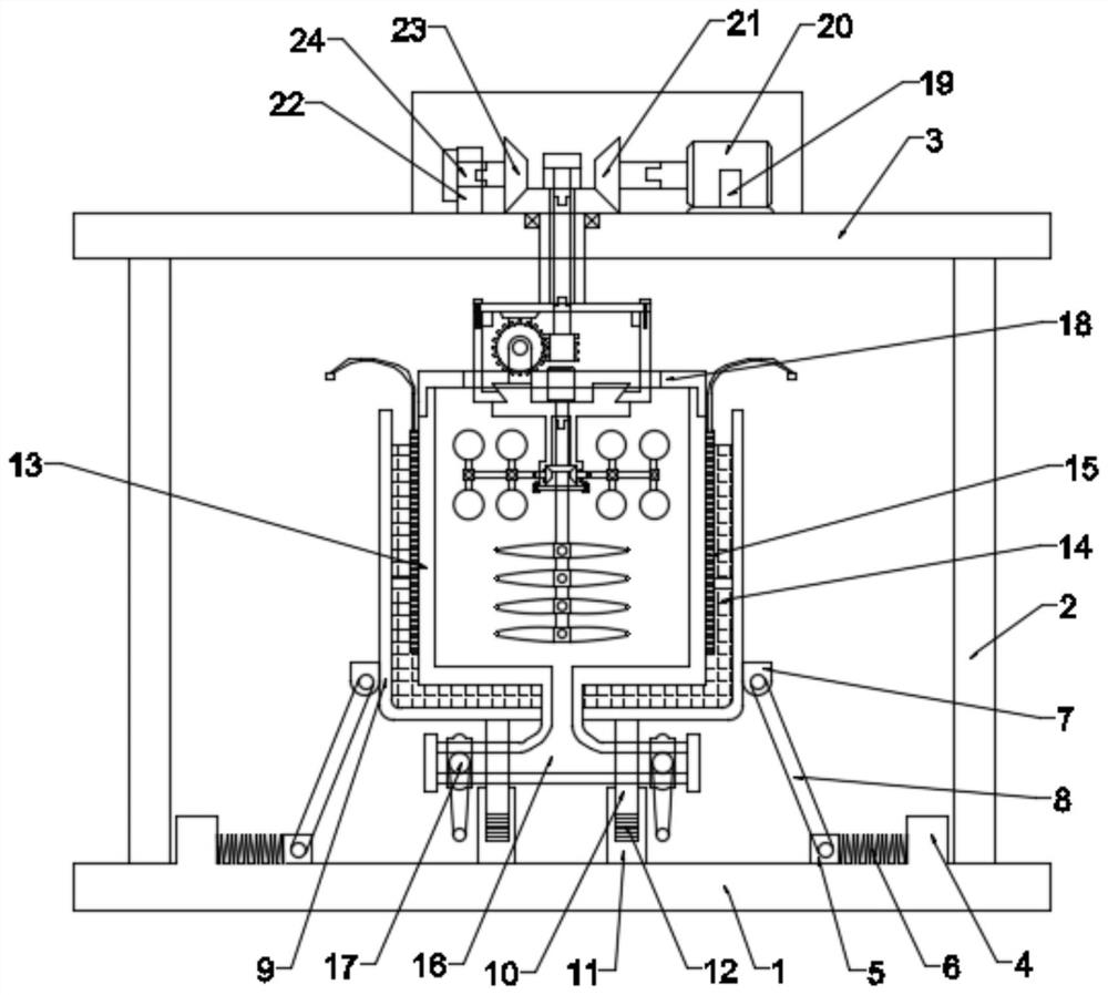
[0021] see figure 1 and Figure 4 , in an embodiment of the present invention, a high-efficiency mixing device for textile dyes for textile machinery, comprising a first base 1, a support column 2 is arranged above the first base 1, and the connection between the support column 2 and the first base 1 Fixedly connected between, above the support column 2 is provided with a second base 3, fixedly connected between the second base 3 and the support column 2; above the first base 1 is provided with a shock-absorbing bearing device, so The shock-absorbing and bearing device includes a first box body 9, a second box body 13 is provided inside the first box body 9, and a feed port 1301 is provided on the front side of the second box body 13, and the second box body 13 is provided with a material inlet 1301. A heating wire 15 is provided on the outer wall of the body 13, a shock absorbing pad 14 is provided between the second box body 13 and the first box body 9; a first box cover 18...

Embodiment 2

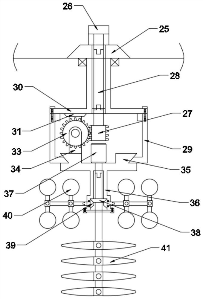
[0026] see Figure 1-3 , the difference from Embodiment 1 is that in the embodiment of the present invention, the power device includes a first motor frame 19, and the first motor frame 19 is fixedly connected to the second base 3, and the first A first motor 20 is arranged above the motor frame 19, which is detachably connected between the first motor 20 and the first motor frame 19, and a first gear 21 is detachably connected to the output shaft of the first motor 20; A limit seat 22 is arranged above the second base 3, and the limit seat 22 is fixedly connected with the second base 3, and a second gear 23 is rotatably connected inside the limit seat 22. The gear 23 is detachably connected to the limit seat 22 through an end buckle 24; a third gear 25 is arranged below the first gear 21 and the first gear 21, and the third gear 25 is connected to the first gear 21. The gears 21 are meshed, and the third gear 25 is meshed with the second gear 23;

[0027] Further, the stirr...


PUM


Abstract

The invention relates to the technical field of textile process raw material processing, and particularly discloses an efficient textile dye mixing device for textile machinery, which comprises a first base, a support column is arranged above the first base, a second base is arranged above the support column, and a damping bearing device is arranged above the first base. The damping bearing devicecomprises a first box body, a second box body is arranged in the first box body, a feeding port is formed in the front side of the second box body, a discharging port is formed in the bottom of the second box body, and a butterfly valve is arranged at an opening of the discharging port; and a stirring device is arranged in the second box body, and a power device is arranged above the second base.The power device drives the stirring device to uniformly stir dye, the stirring range is wide, and the stirring process is stable. The damping bearing device has a protective effect, so that the device is smart in structure, high in degree of freedom of the stirring device, diverse in stirring direction, large in stirring range, uniform in dye stirring effect and convenient to use.

Description

technical field [0001] The invention relates to the technical field of textile process raw material processing, in particular to a high-efficiency mixing device for textile dyes used in textile machinery. Background technique [0002] The core device of the existing textile dye mixing devices for textile machinery is the stirring device, but their stirring methods are too common and old, not only the stirring direction is single, but also the stirring range is not large enough, naturally, the stirring effect is very low. Contents of the invention [0003] The object of the present invention is to provide a textile dyestuff high-efficiency mixing device for textile machinery to solve the problems raised in the above-mentioned background technology. [0004] To achieve the above object, the present invention provides the following technical solutions: [0005] A high-efficiency mixing device for textile dyes for textile machinery, comprising a first base, a support column i...

Claims


Application Information

Patent Timeline
Patent Type & Authority Applications(China)
IPC IPC(8): B01F7/30B01F15/00B01F15/02B01F15/06
CPCB01F27/1125B01F27/1162B01F27/213B01F27/191B01F27/95B01F35/3215B01F35/43B01F35/3204B01F35/7547B01F35/92B01F2035/99B01F2101/30
Inventor 卜源泉
Owner SUZHOU MEILU TEXTILE MASCH ELECTRONICS CO LTD
Learn More