Laser cutting slag removing device

A cleaning device and laser cutting technology, used in laser welding equipment, welding equipment, metal processing equipment, etc., can solve the problems of difficult cleaning, sawtooth deformation of the workbench, affecting the use of the workbench, etc., to achieve the effect of convenient processing and cleaning

Inactive Publication Date: 2021-02-26
十堰良凯工贸有限公司
View PDF0 Cites 0 Cited by
  • Summary
  • Abstract
  • Description
  • Claims
  • Application Information

AI Technical Summary

Problems solved by technology

[0005] The object of the present invention is to provide a laser cutting slag cleaning device to solve the problem that the existing laser cutter proposed in the above background technology needs to frequently process the slag on the sawtooth workbench during use, and the existing cleaning method Usually, iron rods or iron hooks are used to directly hit the serrated workbench, which may cause deformation of the sawtooth of the workbench and affect the use of the workbench. At the same time, the larger cutting slag adheres more strongly and is difficult to clean.

Method used


Image

  • Laser cutting slag removing device
  • Laser cutting slag removing device
  • Laser cutting slag removing device

Examples


Embodiment

[0024] as attached figure 1 to attach Figure 4 Shown:

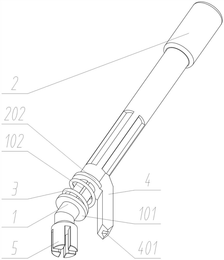
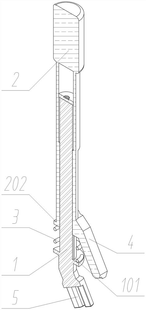
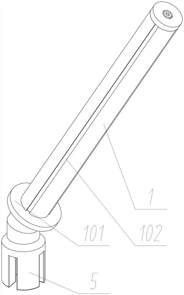
[0025] The invention provides a laser cutting slag cleaning device, comprising: a cleaning rod core 1; a group of holding rods 2 are slidably connected to the top of the cleaning rod core 1; A set of support springs 3 is connected; a set of slag cutting scrapers 5 is fixedly connected to the bottom of the cleaning rod core 1 ; a set of crowbars 4 is fixedly connected to the bottom of the holding rod 2 .

[0026] Wherein, the bottom of the cleaning rod core 1 is provided with an annular protruding limiting spring plate 101, and the lower end of the holding rod 2 is provided with a set of corresponding holding rod limiting plates 202, and the two ends of the supporting spring 3 are fixedly connected to the limiting spring respectively. On the plate 101 and the grip bar limiting plate 202, when in use, the supporting spring 3 is installed in the gap between the limiting spring plate 101 and the grip bar limiting plate 202...


PUM


Abstract

The invention provides a laser cutting slag removing device, belongs to the technical field of laser cutting machine tools, and aims at solving the problems that saw teeth of an existing laser cutterworkbench are likely to deform due to the fact that an iron rod or an iron hook is directly used for knocking a saw-tooth-shaped workbench, and meanwhile large cutting slag adheres firmly and is difficult to remove. According to the laser cutting slag removing device, the top of a removing rod core is connected with a holding rod in a sliding manner; a supporting spring is fixedly connected between the removing rod core and the holding rod; the bottom of the removing rod core is fixedly connected with a cutting slag scraping block; and the bottom of the holding rod is fixedly connected with apry bar. The cutting slag scraping block is arranged to be engaged with sawteeth of the workbench, cutting slag on the workbench is removed, the physical strength of an operator is better saved, the holding rod is pressed to enable the pry bar to serve as a fulcrum to conduct lever motion, firm cutting slag can be shoveled, more labor is saved during removing, and subsequent machining and removingare facilitated.

Description

technical field [0001] The invention relates to the technical field of laser cutting machine tools, in particular to a laser cutting slag cleaning device. Background technique [0002] Laser cutting In order to prevent the cutting machine from causing greater damage to the workbench, the workbench is usually serrated to reduce the contact area of ​​the tip and avoid the possibility that the cutting machine will cut it together. However, due to the increased area of ​​the serration, the laser cutting machine During the working process, a large amount of cutting slag will be produced and solidified on the jagged workbench. The continuous accumulation of cutting slag will cause the plate to be unable to lay flat and cause positioning errors. Partial. [0003] Based on the above, I found that the existing laser cutter needs to frequently deal with the cutting slag on the serrated workbench during use. The existing cleaning method usually directly uses iron rods or iron hooks to...

Claims


Application Information

Patent Timeline
Patent Type & Authority Applications(China)
IPC IPC(8): B23K26/16B23K26/38
CPCB23K26/16B23K26/38
Inventor 彭玉林金学锋
Owner 十堰良凯工贸有限公司
Why Eureka
Try Eureka