Screw rotor double-body machining method and device
A processing method and technology of a processing device are applied in the field of screw rotor double-body processing method and processing device to achieve the effects of saving material cost and manufacturing cost, making up for material waste and improving production efficiency
- Summary
- Abstract
- Description
- Claims
- Application Information
AI Technical Summary
Problems solved by technology
Method used
Image
Examples
Embodiment 1
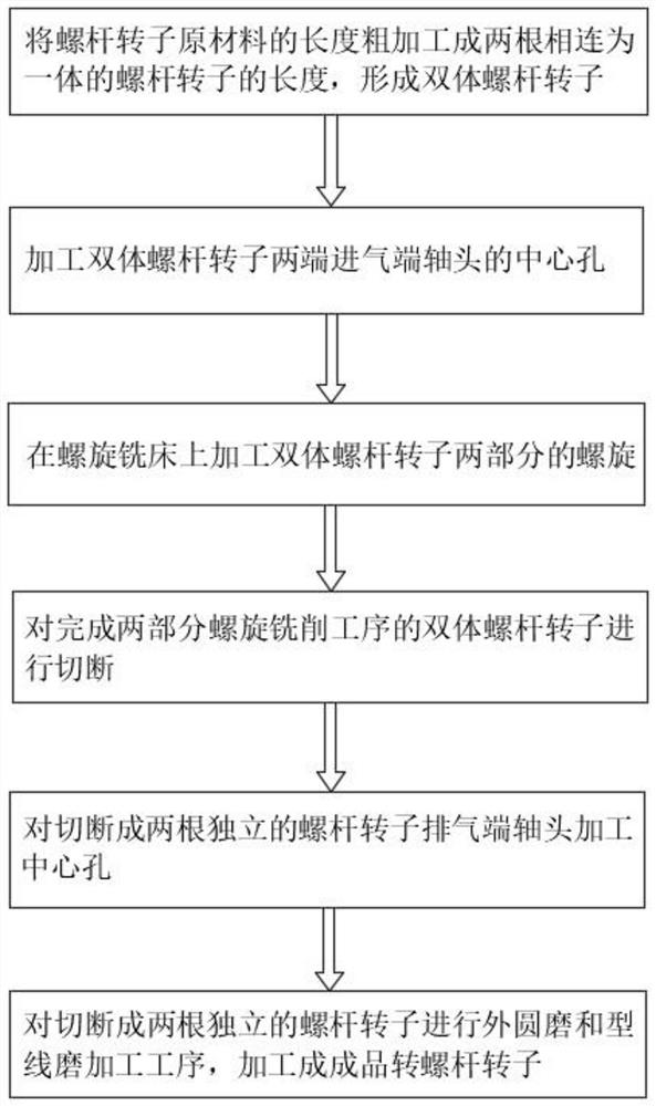
[0032] Such as figure 1 As shown, a double-body processing method of a screw rotor in this embodiment includes the following steps:
[0033] Step 1. According to the design size of the screw rotor, the length of the raw material of the screw rotor is roughly machined into the length of two connected screw rotors to form a double-body screw rotor. The axial middle part of the two connected double-body screw rotors is the exhaust end shaft of the two screw rotors, and the two ends of the axial direction are the intake end shafts of the double-body screw rotor. The length of the exhaust end shaft is There is a sawing off and a finishing allowance for the shaft head of the exhaust end. During processing, first process the diameter of the helical part of the double-body screw rotor, then process the shaft diameters of the intake ends at both ends of the double-body screw rotor, and finally process the shaft diameters of the two connected exhaust ends located in the middle of the d...
Embodiment 2
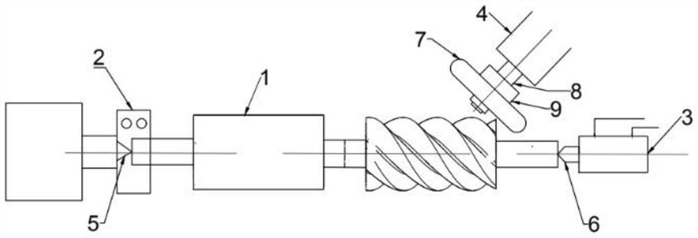
[0040] Such as Figure 2 ~ Figure 3 As shown, the screw rotor double-body processing device of this embodiment includes a drive head 2 connected to the drive head of the helical milling machine, a hydraulic tailstock 3 arranged at the tail end of the helical milling machine, and is arranged above the helical milling machine and located at the drive head 2 and the hydraulic tailstock. The milling cutter disc drive mechanism 4 between the seats 3.
[0041] The inner cavity of the driving head 2 is provided with a driving head tip 5, which is used to support and position the shaft head at one end of the screw rotor 1, and the driving head 2 uses a clamping device to clamp the shaft head at one end of the screw rotor 1 to process the screw rotor When the spiral of 1 drives the screw rotor 1 to rotate.
[0042] The tailstock center 6 is connected to the side of the hydraulic tailstock 3 facing the drive head, the tailstock center 6 is concentric with the axis of the drive head 5, ...
PUM
 Abstract
Description
Claims
Application Information
 - R&D
- Intellectual Property
- Life Sciences
- Materials
- Tech Scout
- Unparalleled Data Quality
- Higher Quality Content
- 60% Fewer Hallucinations
Browse by: Latest US Patents, China's latest patents, Technical Efficacy Thesaurus, Application Domain, Technology Topic, Popular Technical Reports.
© 2025 PatSnap. All rights reserved.Legal|Privacy policy|Modern Slavery Act Transparency Statement|Sitemap|About US| Contact US: help@patsnap.com


