Deburring device for motor shell production

A motor casing and burr technology, which is used in grinding drive devices, grinding/polishing safety devices, and parts of grinding machine tools, etc., can solve problems such as cleaning dead corners, inability to deburr the bottom outer wall and circumferential inner wall of the motor casing, etc. , to achieve the effect of reducing the dead angle of cleaning

Inactive Publication Date: 2021-02-26
龚爽
View PDF10 Cites 6 Cited by
  • Summary
  • Abstract
  • Description
  • Claims
  • Application Information

AI Technical Summary

Problems solved by technology

[0005] The purpose of the present invention is to solve the shortcomings in the prior art that the bottom outer wall and the circumferential inner wall of the motor casing cannot be deburred during the operation process, and there is a shortcoming of cleaning dead corners, and a kind of deburring device for the production of the motor casing is proposed

Method used


Image

  • Deburring device for motor shell production
  • Deburring device for motor shell production
  • Deburring device for motor shell production

Examples


Embodiment Construction

[0032] The technical solution of this patent will be further described in detail below in conjunction with specific embodiments.

[0033] Embodiments of the present patent are described in detail below, examples of which are shown in the drawings, wherein the same or similar reference numerals designate the same or similar elements or elements having the same or similar functions throughout. The embodiments described below by referring to the figures are exemplary and are only used for explaining the patent, and should not be construed as limiting the patent.

[0034] In the description of this patent, it is to be understood that the terms "center", "upper", "lower", "front", "rear", "left", "right", "vertical", "horizontal", The orientation or positional relationship indicated by "top", "bottom", "inner", "outer", etc. is based on the orientation or positional relationship shown in the drawings, and is only for the convenience of describing this patent and simplifying the des...


PUM


Abstract

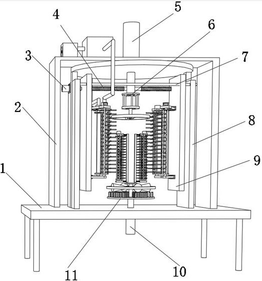
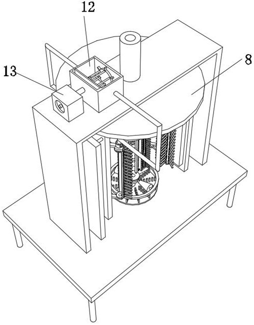
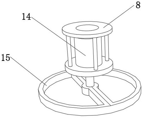
The invention discloses a deburring device for motor shell production, relates to the technical field of motor shell deburring devices, and aims to reduce burr cleaning dead angles. The deburring device specifically comprises a base, a motor shell and a reverse distance adjusting mechanism, two moving plates are slidably connected to the outer wall of the distance adjusting mechanism, two rotatingframes are fixed to the inner wall of one side of each of the two moving plates through bolts, and two connecting rods are rotatably connected to the inner wall of each of the two rotating frames through rotating shafts; and the inner walls of one sides of the two connecting rods located on the same side are rotationally connected with the same first hole-shaped brush roller, and the outer wallsof one sides of the two connecting rods located on the two sides are connected with the same tension spring in a clamped mode. By arranging the four first hole-shaped brush rollers, the circumferential outer walls of the moving plates can play a role in clamping the circumferential outer wall of the motor shell in the moving process of the moving plates, and therefore burrs on the circumferentialouter wall of the motor shell can be removed through brushes arranged on the circumferential outer walls of the first hole-shaped brush rollers.

Description

technical field [0001] The invention relates to the technical field of deburring devices for motor casings, in particular to a deburring device for motor casing production. Background technique [0002] The motor shell is used to accommodate and protect the coils inside the motor. During the production process of the motor shell, the surface needs to be deburred to ensure the smoothness of the surface and facilitate the subsequent painting and polishing of the surface , the existing deburring device has a small scope of application, and there is a dead angle for cleaning. [0003] After searching, the Chinese patent application number is CN201920939188.4, which discloses a deburring device for the production of explosion-proof motor shells, including a box body, a rotating motor is arranged at the bottom of the box, and a rotating shaft is arranged at the top of the rotating motor. The top of the shaft is provided with a base, the side wall of the inner cavity of the box is...

Claims


Application Information

Patent Timeline
Patent Type & Authority Applications(China)
IPC IPC(8): B24B9/04B24B5/12B24B27/00B24B41/06B24B47/00B24B47/12B24B47/22B24B55/06B24B55/12
CPCB24B5/12B24B9/04B24B27/0076B24B41/061B24B47/00B24B47/12B24B47/22B24B55/06B24B55/12
Inventor 龚爽
Owner 龚爽
Why Eureka
Try Eureka