
Mask slicing machine

A slicing machine and mask technology, applied in the field of mask slicing machine, can solve the problems of inconvenient replacement of the dissolving roller, affecting the roll cutting, inconvenient debugging, etc., and achieve the effect of overcoming the inconvenience of replacing the driving roller, reducing the production cost, and avoiding repeated debugging.

Pending Publication Date: 2021-02-26
SUZHOU TRAPEZE ASSEMBLY AUTOMATION CO LTD
View PDF0 Cites 0 Cited by
  • Summary
  • Abstract
  • Description
  • Claims
  • Application Information

AI Technical Summary

Problems solved by technology

As a result, when the roller knife needs to be replaced, it needs to be replaced as a whole
In addition, due to the short bridge of the nose, only the upper part of the blade of the roller knife can perform the role of rolling cutting, and the blades in the rest of the area cannot actually perform the role of rolling cutting;
[0004] (2) The fusion roller often needs to be replaced, but in the existing mask machine, due to the unreasonable setting of the ultrasonic mechanism and the fusion roller, it is inconvenient to replace the melting roller;
[0005] (3) The cost of the ultrasonic marking mechanism is relatively high, and it is not easy to debug, which is not conducive to reducing the production cost of the mask;
[0006] (4) Since the shape knife is pressed on the driving roller during roller cutting, it is so easy to form an imprint on the driving roller, which will affect the progress of roller cutting
Therefore, the driving roller needs to be replaced frequently, but the driving roller of the existing mask die-cutting equipment is relatively inconvenient to replace because it is connected with the motor

Method used


Image

  • Mask slicing machine
  • Mask slicing machine
  • Mask slicing machine

Examples


Embodiment Construction

[0035] The present invention will be described in detail below in conjunction with various embodiments, but it should be noted that these embodiments are not limitations of the present invention, and those of ordinary skill in the art can make functional, method, or structural equivalent transformations or replacements based on these embodiments. , all fall within the protection scope of the present invention.

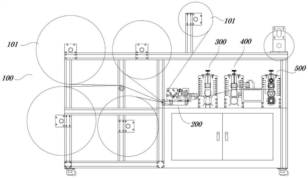
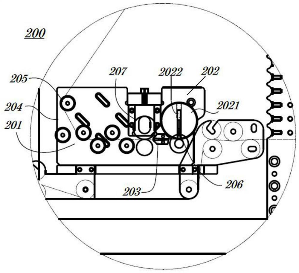
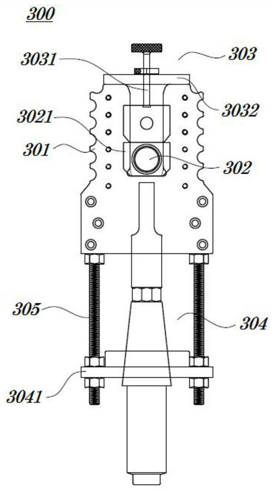
[0036] Such as figure 1 As shown, an embodiment of the present invention provides a mask slicing machine, which includes: an unwinding device 100 , a nose bridge strip roller cutting device 200 , an ultrasonic welding device 300 , a flat coding device 400 and a roller cutting device 500 .

[0037] 【Unwinding device 100】

[0038] The unwinding device 100 includes: a plurality of unwinding rollers 101 . Wherein, the plurality of unwinding rollers 101 are installed on the frame of the mask slicer, and the plurality of unwinding rollers 101 provide the material belt of t...


PUM


Abstract

The invention provides a mask slicing machine. The mask slicing machine comprises an unwinding device, a nose bridge strip roller cutting device, an ultrasonic welding device, a flattening and code spraying device and a roller cutting device. According to the mask slicing machine, the cutting edge is inserted into a roller cutter body in the radial direction, the cutting edge can be independentlyreplaced when the cutting edge needs to be replaced, and the whole roller cutter is prevented from being replaced; an ultrasonic mechanism is arranged below a welding roller, so that the ultrasonic mechanism does not hinder the replacement of the welding roller; by adopting an ink-jet marking mode, the manufacturing cost of the mask is reduced; meanwhile, the ink-jet marking mode is simple in process, repeated debugging is not needed, and the actual production and manufacturing requirements of the mask are met; by additionally arranging a cutting die bottom roller which is detachably arranged,the cutting die bottom roller and a shape cutter form a roller cutting space, and therefore the shape cutter is prevented from being directly pressed on a drive roller; and during replacement, the cutting die bottom roller can be directly replaced, and the problem that the drive roller is inconvenient to replace in the prior art is solved.

Description

technical field [0001] The invention relates to the technical field of mask slicers, in particular to a mask slicer. Background technique [0002] At present, the existing mask slicer needs to roll-cut the bridge of the nose, and then go through the processes of welding, smoothing, and roll-cutting to obtain the intermediate product of the mask. Yet existing mask slicer has following problems: [0003] (1) The blade of the existing roller cutter for cutting off the bridge of the nose is arranged on the roller cutter body in the axial direction, and extends from one end to the other end. As a result, when the roller knife needs to be replaced, it needs to be replaced as a whole. In addition, due to the short bridge of the nose, only the upper part of the blade of the roller knife can perform the role of rolling cutting, and the blades in the rest of the area cannot actually perform the role of rolling cutting; [0004] (2) The fusion roller often needs to be replaced, but ...

Claims


Application Information

Patent Timeline
Patent Type & Authority Applications(China)
IPC IPC(8): B29D99/00A41D13/11A41H42/00
CPCA41D13/11A41H42/00B29D99/0071
Inventor 宋海根廖成平吴波朱红亮
Owner SUZHOU TRAPEZE ASSEMBLY AUTOMATION CO LTD
Learn More