
Self-adjusting selective rainwater collecting device

A rainwater collection device and selective technology are applied in the field of self-adjusting and selective rainwater collection devices, which can solve the problem of inability to selectively collect rainwater, and achieve the effects of ensuring smoothness, reducing the cost of purification and reuse, and avoiding pollution.

Inactive Publication Date: 2021-02-26
汤姗姗
View PDF8 Cites 2 Cited by
  • Summary
  • Abstract
  • Description
  • Claims
  • Application Information

AI Technical Summary

Problems solved by technology

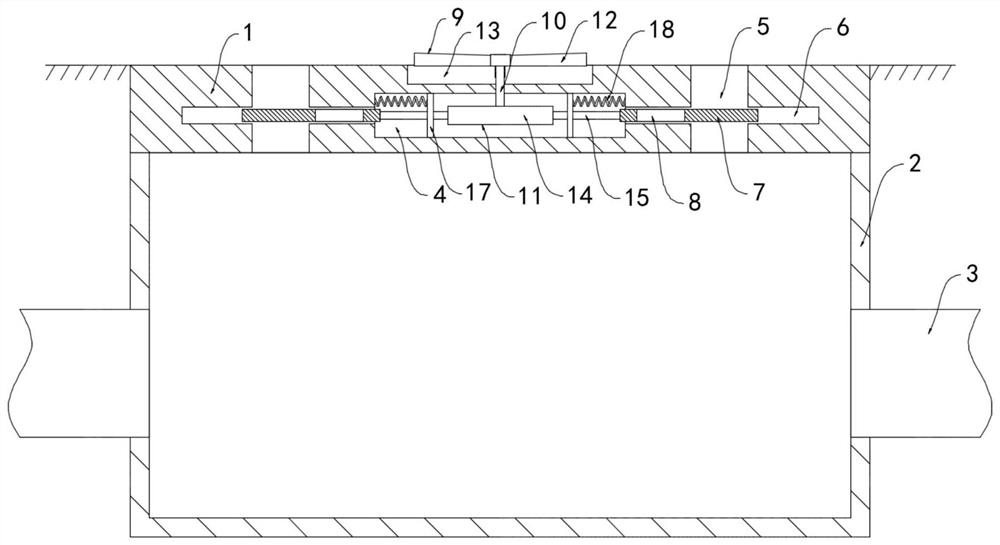
[0005] The purpose of the present invention is to provide a self-regulating selective rainwater collection device that can selectively collect rainwater for the problem that rainwater cannot be selectively collected

Method used


Image

  • Self-adjusting selective rainwater collecting device
  • Self-adjusting selective rainwater collecting device
  • Self-adjusting selective rainwater collecting device

Examples


Embodiment 1

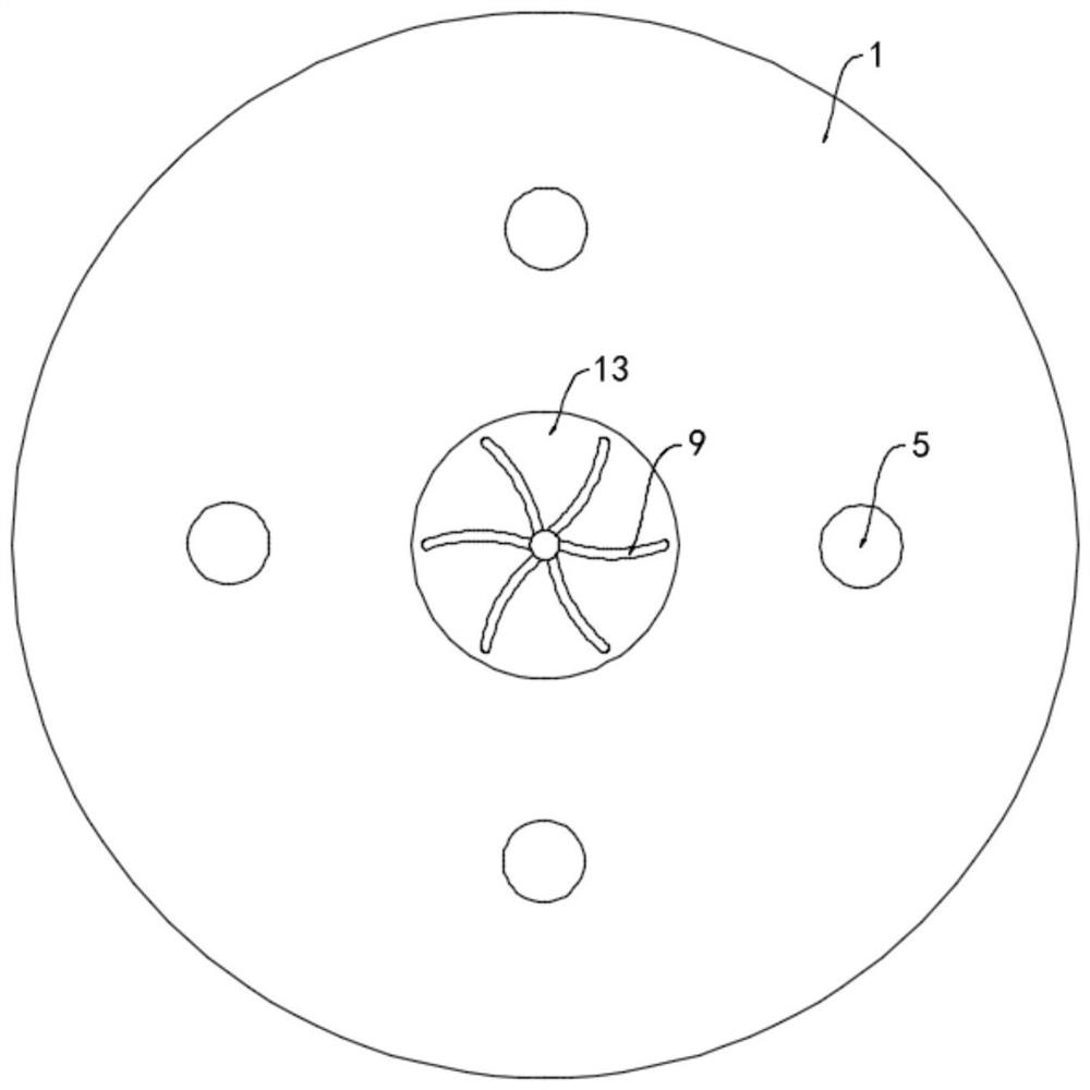
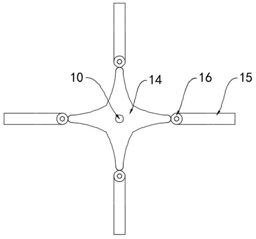
[0023] Such as Figure 1-4 As shown, a self-regulating selective rainwater collection device includes a base 1, the base 1 is embedded on the road surface and the upper surface of the base 1 is flush with the road surface, a water tank 2 is provided under the base 1, and the sides on both sides of the water tank 2 The walls are provided with drainage pipes 3 communicating with the reservoir, the base 1 is provided with a cavity 4, and the base 1 is penetrated with a plurality of diversion holes 5, and the plurality of diversion holes 5 are ring-shaped with the cavity 4 as the center Arranged in an array, the side wall of the diversion hole 5 is provided with a chute 6 , a horizontal sealing baffle 7 is slidably connected to the chute 6 , and a through hole 8 matching the diversion hole 5 is opened in the sealing baffle 7 .

[0024] The upper surface of the base 1 is provided with a water wheel 9, the water wheel 9 is composed of a plurality of water-repelling plates 12, and th...

Embodiment 2

[0030] Such as Figure 5 As shown, the difference between this embodiment and Embodiment 1 is that an annular filter screen 19 is provided on the inner wall of the water tank 2, and the lower end of the rotating shaft 10 extends into the water tank 2 and is fixedly connected with the annular filter screen 19 through a connecting rod.

[0031] In this embodiment, the annular filter screen 19 can filter the impurities carried in the rainwater to improve the water purification effect. When the rotating shaft 10 rotates, it drives the annular filter screen 19 to rotate, and the annular filter screen 19 rotates periodically to the inlet of the drain pipe 3 end, reduce the possibility that the ring filter screen 19 is blocked and the rainwater cannot be discharged from the water tank 2.


PUM


Abstract

The invention belongs to the field of sponge city construction, and particularly relates to a self-adjusting selective rainwater collecting device. The self-adjusting selective rainwater collecting device comprises a base, wherein the base is embedded in a road surface, the upper surface of the base is flush with the road surface, a water tank is arranged below the base, drainage pipes which communicates with a reservoir are arranged on the side walls of both sides of the water tank, a cavity is formed in the base, a plurality of flow guide holes are formed in the base in a penetrating mode, the plurality of flow guide holes are distributed in an annular array with the cavity as the center of a circle, chutes are formed in the side walls of the flow guide holes, horizontal sealing bafflesare connected to the interiors of the chutes in a sliding mode, through holes which are matched with the flow guide holes are formed in the sealing baffles, a water wheel is arranged on the upper surface of the base, and a rotating shaft is in sliding connection to the interior of the water wheel in a penetrating mode. According to the self-adjusting selective rainwater collecting device, rainwater can be selectively collected, so that road surface impurities are prevented from entering the water tank along with the rainwater so as not to cause pollution, and the rainwater purifying and recycling cost is reduced.

Description

technical field [0001] The invention belongs to the field of sponge city construction, and in particular relates to a self-regulating selective rainwater collection device. Background technique [0002] Sponge city refers to a city that can act like a sponge and has good adaptability to environmental changes and natural disasters. When it rains, it absorbs, stores, infiltrates, and purifies water. When necessary, it discharges and utilizes the stored water to improve Urban Ecosystem Functions and Reduction of Urban Flood Disasters. [0003] In the prior art, a rainwater collection device is used to collect and utilize rainwater. However, the traditional rainwater collection device has a simple structure and a single function, and cannot selectively collect rainwater. During light rain, the rainfall is small and the amount of rainwater collected is also small. However, the rainwater is washed by the confluence of the bottom surface, which contains a lot of dust and impuritie...

Claims


Application Information

Patent Timeline
Patent Type & Authority Applications(China)
IPC IPC(8): E03B3/02B01D29/00
CPCE03B3/02B01D29/018Y02A20/108
Inventor 汤姗姗
Owner 汤姗姗
Learn More