
Split type pneumatic control button

A split-type, button technology, applied in flushing equipment with water tanks, flushing toilets, water supply devices, etc., can solve the problems of poor reliability, large number of parts, and large use limitations, and achieves strong applicability and simple structure. And compact, easy to install effect

Pending Publication Date: 2021-02-26
QINGHUAN TUODA (SUZHOU) ENVIRONMENTAL TECH CO LTD
View PDF7 Cites 0 Cited by
  • Summary
  • Abstract
  • Description
  • Claims
  • Application Information

AI Technical Summary

Problems solved by technology

[0018] The purpose of the present invention is to provide a split type air control button to solve the problem that the touch button used in the vacuum toilet in the prior art has a large use limitation when it adopts an integrated structure, and when the split structure is used, the number of parts is large and the The problem of poor reliability

Method used


Image

  • Split type pneumatic control button
  • Split type pneumatic control button
  • Split type pneumatic control button

Examples


Embodiment Construction

[0031] Below in conjunction with specific embodiment, content of the present invention is described in further detail:

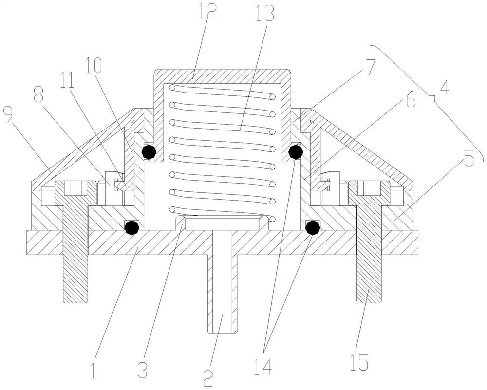
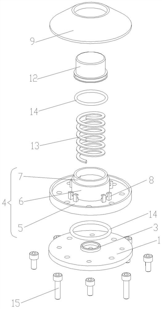
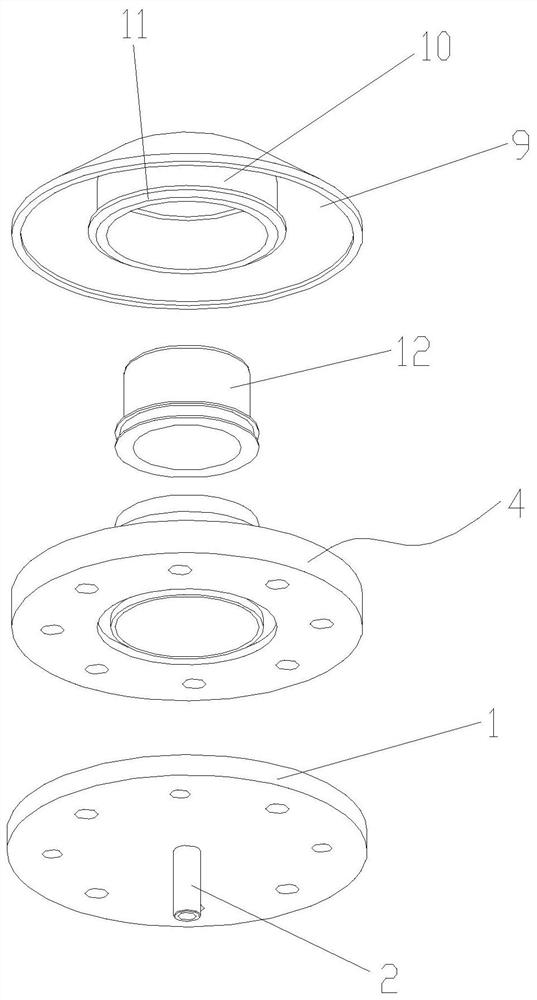
[0032] Such as figure 1, figure 2 As shown, a split-type air control button includes a base 1 fixedly arranged coaxially in sequence, an intermediate housing 4 and an outer shell 9, a button cap 12 nested inside the intermediate housing 4, and the button cap 12 is pressed. And the reset spring 13 for reset; the button cap 12 forms a cavity with the inner wall of the middle housing 4 and the end surface of the base 1, and the middle part of the base 1 has a ventilator connected with the cavity.

[0033] More specifically, the base 1 has a flat columnar structure, with a vent tube 2 extending outwards in the middle and open at both ends, and a stop snap ring 3 at the end opposite to the direction in which the vent tube 2 extends.

[0034] The intermediate housing 4 includes a connection plate 5 and a central sleeve 6 arranged coaxially in an integrated stru...


PUM


Abstract

The invention relates to a split type pneumatic control button, which comprises a base, a middle shell, an outer shell, a button cap and a reset spring, wherein the base, the middle shell and the outer shell are coaxially and fixedly arranged in sequence, the button cap is nested in the middle shell, and the reset spring is used for pressing and resetting the button cap. The button cap, the innerwall of the middle shell and the end face of the base form a cavity, and a vent pipe communicated with the cavity is arranged in the middle of the base. The split type pneumatic control button is applied to the field of vacuum closestools and used for controlling a pneumatic controller in the vacuum closestool, the split type structural design is adopted between the button and the pneumatic controller, the vent pipe is used for connection, and installation is convenient; and for the structure of the split type pneumatic control button, a spring reset piston type structure is adopted, the structure is simple and compact, and the applicability is high.

Description

technical field [0001] The present invention relates to the technical field of vacuum sewage collection, transportation and treatment, wherein the vacuum sewage collection technology refers to front-end devices or products that collect sewage at the source of sewage, including but not limited to various kitchens (such as toilets, urinals, shower rooms, etc.) , bathtubs, etc.) and sanitary products (such as vegetable sinks, dishwashers, etc.); vacuum sewage transportation technology refers to the related technologies that efficiently transport the sewage collected by front-end devices or products to sewage post-treatment equipment, including the core components There are vacuum pumping stations, sewage collection tanks, underground vacuum conveying pipe network systems, vacuum wells, fault detection and diagnosis systems, etc.; vacuum sewage treatment technology refers to post-processing equipment or devices, the main function of which is to separate solids and liquids from cent...

Claims


Application Information

Patent Timeline
Patent Type & Authority Applications(China)
IPC IPC(8): E03D5/09E03D5/02E03D11/13
CPCE03D5/024E03D5/09E03D11/13
Inventor 崔利兴邓永峰
Owner QINGHUAN TUODA (SUZHOU) ENVIRONMENTAL TECH CO LTD
Features
  • Generate Ideas
  • Intellectual Property
  • Life Sciences
  • Materials
  • Tech Scout
  • Unparalleled Data Quality
  • Higher Quality Content
  • 60% Fewer Hallucinations
Learn More