Device and method for accurately positioning reinforcing steel bars

A fingerprint device and precise positioning technology, which is applied to buildings, building reinforcements, building components, etc., can solve the problems of large position error of steel bars, inefficient construction of concrete structures for durability of concrete structures, and large thickness deviations of steel protective layers. Guaranteed quality, simple and convenient connection method, and uniform thickness

Pending Publication Date: 2021-02-26
HUAZHONG UNIV OF SCI & TECH
View PDF5 Cites 1 Cited by
  • Summary
  • Abstract
  • Description
  • Claims
  • Application Information

AI Technical Summary

Problems solved by technology

When the circular ribbed steel bar is placed on the pad, the contact surface between the steel bar and the pad is generally in point or line contact. When the on-site construction activity load and operation disturbance are applied, the pad will be damaged or displaced due to the concentrated load. The thickness of the protective layer of steel bars cannot be guaranteed, let alone the position of the steel bars, resulting in a large deviation in the thickness of the steel bar cover in the cast-in-place reinforced concrete components, and a large error in the position of the steel bars in the prefabricated reinforced concrete structure, which cannot ensure accurate connection, resulting in durable concrete structures problems and inefficient construction of prefabricated reinforced concrete structures

Method used


Image

  • Device and method for accurately positioning reinforcing steel bars
  • Device and method for accurately positioning reinforcing steel bars
  • Device and method for accurately positioning reinforcing steel bars

Examples


Embodiment

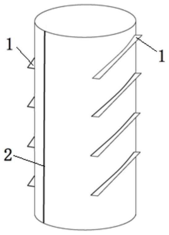
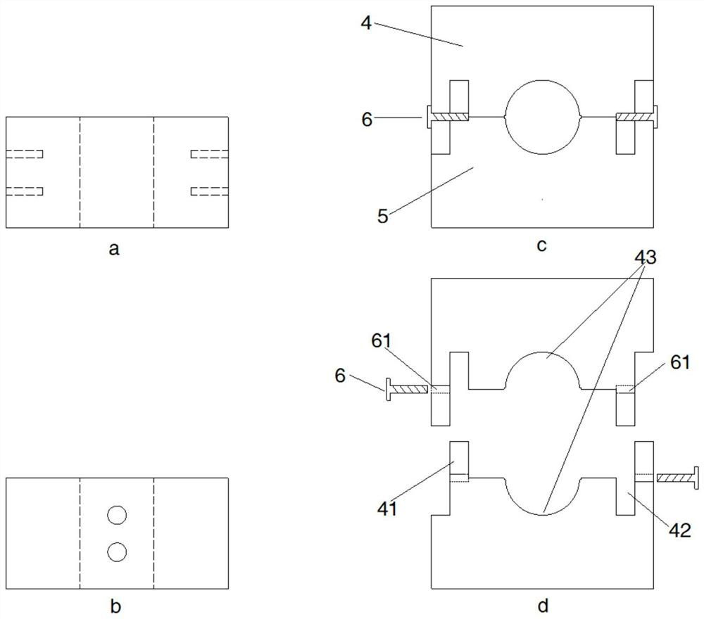
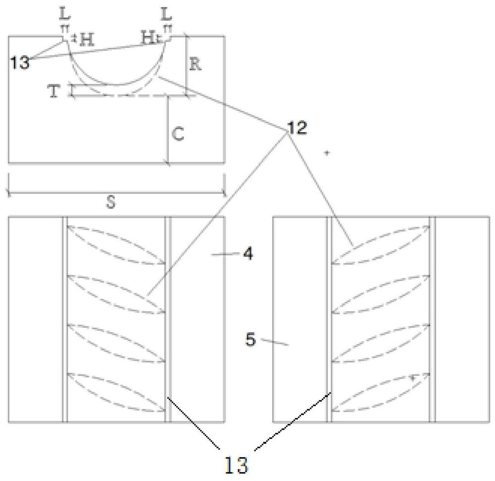
[0031] The prefabricated concrete beam will be described as an example below. The size of the snap-fit ​​fingerprint module set on the prefabricated beam is 80mm*80mm*40mm. image 3From the point of view, the number of horizontal ribs and female ribs set in the groove of the fingerprint module is determined according to the specifications of the fingerprint module and the steel bar, generally not less than two. The width S of the fingerprint module should not be less than twice the diameter R of the steel bar, and the thickness C of the protective layer of the steel bar at the edge of the component must meet the requirements of the specification. The female longitudinal rib pattern is a square groove surface with a height of H and a width of L. When the fingerprint module is fastened, the longitudinal female rib pattern and the longitudinal rib of the steel bar are tightly occluded. Its specification matches the longitudinal rib of the steel bar, H is half the height of the lo...


PUM


Abstract

The invention relates to a device and method for accurately positioning reinforcing steel bars in a prefabricated part. The device comprises fingerprint module units and supporting connection units, wherein the fingerprint module units are fixedly connected through the supporting connection units, each fingerprint module unit is formed by the enclosing of a first fingerprint module and a second fingerprint module, a groove is formed in the middle of each of the two fingerprint modules, after buckling, the grooves of the fingerprint module units form steel bar channels matched with the steel bars, female rib lines are arranged in the grooves, the steel bars in the prefabricated part are meshed with the plurality of fingerprint module units, and the fingerprint module units are relatively fixed through the supporting connecting units, so that the steel bars do not move in the relative positions in the prefabricated part and do not rotate, the fingerprint module units, the supporting connecting units and the reinforcing steel bars jointly form a stable rigid frame, that is, the reinforcing steel bars can be accurately positioned, the accuracy of the positions of the reinforcing steelbars in the prefabricated part is guaranteed, and the strength, rigidity and overall performance of connecting areas are not damaged after all the parts are connected. The use method is simple and convenient, can form standardization of manufacturing and construction of the prefabricated reinforced concrete part, and is suitable for large-scale popularization.

Description

technical field [0001] The patent of the present invention relates to the technical field of construction of prefabricated assembled reinforced concrete structures, in particular to a fingerprint device and method for precise positioning of steel bars. Background technique [0002] At present, as the country vigorously promotes the process of industrialization of new buildings and the continuous upgrading of lean construction, prefabricated structures are more and more widely used in the construction field. The core of prefabricated structural system construction is the connection area between components. The strength and stiffness of the connection area directly determine the overall performance of the structural system. In actual construction, prefabricated components such as prefabricated beams, columns, beam slabs, and stairs are hoisted and connected to form a reasonable structural stress system. In the prefabricated reinforced concrete structural system, the connectio...

Claims


Application Information

Patent Timeline
Patent Type & Authority Applications(China)
IPC IPC(8): E04C5/16E04C5/18
CPCE04C5/163E04C5/18
Inventor 赵挺生师玉栋胡俊杰冯楚璇
Owner HUAZHONG UNIV OF SCI & TECH
Why Eureka
Try Eureka