Cup-shaped flexible gear cylinder structure

A technology of flexible splines and cylinders, applied in belts/chains/gears, portable lifting devices, components with teeth, etc., can solve the problems of small stress transition area, complex stress concentration, and no change in wall thickness, etc., to achieve Improve the bearing capacity of flexsplines, improve fatigue resistance, and reduce the effect of stress amplitude

Pending Publication Date: 2021-02-26
BEIJING RES INST OF PRECISE MECHATRONICS CONTROLS
View PDF6 Cites 1 Cited by
  • Summary
  • Abstract
  • Description
  • Claims
  • Application Information

AI Technical Summary

Problems solved by technology

[0003] The commonly used structures of flexsplines are cup-shaped, top-hat-shaped, ring-shaped, etc. Among them, the structure of cup-shaped flexsplines is the most complex and has serious stress concentration phenomenon, which makes the flexsplines prone to fatigue damage.
At present, the commonly used cylinder structure of cup-shaped flexible splines is a straight cylinder, that is, a smooth and thin-walled cylinder is used, and the wall thickness does not change. Although a circular arc transition is used between the cylinder body and the bottom of the barrel, there is still a phenomenon of stress concentration; the current flexible spline cylinder The bottom structure generally adopts an inclined line with an angle of 1-3° as the transition structure. Although this structure realizes the design of equal-strength beams to a certain extent, the stress transition zone in the transition zone between the tube bottom web plate and the tube bottom flange is small. Stress concentration still prominent

Method used


Image

  • Cup-shaped flexible gear cylinder structure
  • Cup-shaped flexible gear cylinder structure
  • Cup-shaped flexible gear cylinder structure

Examples


Embodiment

[0042] A cup-shaped flexspline cylinder structure is used to reduce the stress concentration caused by elastic deformation of the flexspline and improve the load-bearing capacity of the flexspline.

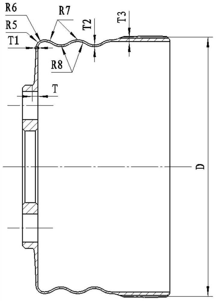
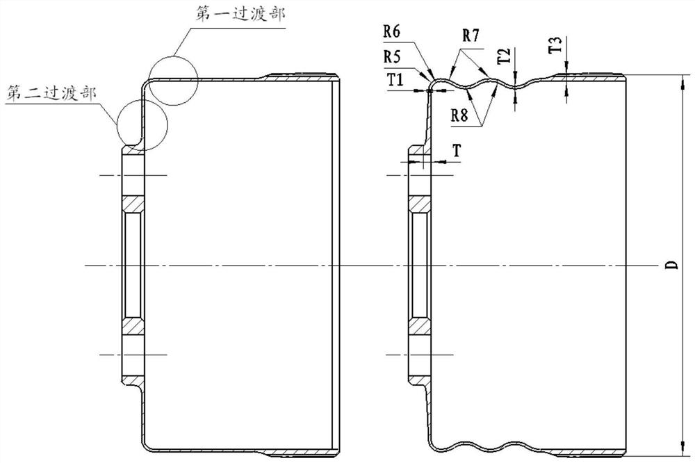
[0043] 1) The transition zone of the cylinder adopts a corrugated structure, the outermost diameter of the wave crest is consistent with the maximum outer diameter of the flexspline cylinder, and the wave height is 2 to 4 times the maximum deformation of the cam; figure 1 shown.

[0044] The flexible spline adopts a corrugated structure, that is, 1 wave crest + 2 wave troughs.

[0045] T3=(75+Z R / 4)×D / 10000, where Z is R The number of flexspline teeth, D is the diameter of the pitch circle of the flexspline tooth, and the wall thickness of the T3 flexspline ring gear.

[0046] T2=(0.52~0.55)×T3, T2 is the wall thickness of the cylinder.

[0047] R7-R8=T2, where the crest arc radius R7 and the trough arc radius R8.

[0048] R6=(0.02~0.03)×D.

[0049] R5=(R6+T2)×(0.9~1.0).

...


PUM

PropertyMeasurementUnit
Arc radiusaaaaaaaaaa
Arc radianaaaaaaaaaa

Abstract

A cup-shaped flexible gear cylinder structure comprises a cylinder side wall and a cylinder bottom connected to the cylinder side wall, wherein a through hole is formed in the middle of the cylinder bottom, and the opposite positions of the two sides of the through hole are each provided with a flange hole; a corrugated structure and a first transition part are arranged at the positions, close tothe cylinder bottom, of the cylinder side wall, the corrugated structure is connected to the first transition part, and the first transition part is connected to the cylinder bottom; the thicknesses of all parts of the corrugated structure is equal, and the wave crest arc radius of the corrugated structure is unequal to the wave trough arc radius of the corrugated structure; the first transition part is composed of two sections of arcs with different radiuses, and the thickness of the first transition part is smaller than that of the corrugated structure; and a second transition part is arranged at the position, close to the flange hole, of the cylinder bottom, the second transition part is composed of four sections of arcs with different radiuses, and the radiuses of the four sections ofarcs are sequentially reduced in the direction from the cylinder side wall to the through hole. The phenomena of stress concentration at the transition area of the cylinder bottom and the cylinder body and stress concentration at the transition area of the cylinder bottom radial plate and the cylinder bottom flange can be greatly reduced, so that anti-fatigue capacity is improved, and bearing capacity of the flexible gear is improved.

Description

technical field [0001] The invention relates to a cup-shaped flexspline cylinder structure, which is used to reduce the stress concentration of the flexspline caused by elastic deformation and improve the load-bearing capacity of the flexspline. Background technique [0002] As the weakest part of the harmonic reducer and the most prone to fatigue damage, the flexspline has a great influence on the load and life of the flexspline. As an elastic deformation body, the flexspline is in a state of alternating stress under the forced deformation force of the cam, and it is easy to produce stress concentration and uneven distribution of load stress in the transition area of ​​the deformation zone. [0003] The commonly used structures of flexsplines are cup-shaped, hat-shaped, ring, etc. Among them, the structure of cup-shaped flexsplines is the most complex and has serious stress concentration phenomenon, which makes the flexsplines prone to fatigue damage. At present, the commo...

Claims


Application Information

Patent Timeline
IPC IPC(8): F16H49/00F16H55/17F16H55/08
CPCF16H49/001F16H55/17F16H55/0833
Inventor 侍威张兆晶豆永强郑继贵李建军
Owner BEIJING RES INST OF PRECISE MECHATRONICS CONTROLS
Why Eureka
Try Eureka