Method and equipment for producing air product based on cryogenic distillation
A technology of air and products, applied in the field of producing air products based on cryogenic distillation, which can solve problems such as bubbles and achieve accurate and safe results
- Summary
- Abstract
- Description
- Claims
- Application Information
AI Technical Summary
Problems solved by technology
Method used
Image

Examples
Embodiment Construction
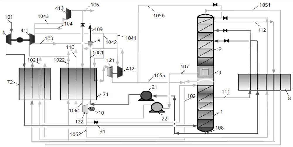
[0047] The present invention will be further described below through specific embodiments in conjunction with the accompanying drawings. These embodiments are only used to illustrate the present invention, and are not intended to limit the protection scope of the present invention.
[0048] In the present invention, the term "feed air" refers to a mixture mainly comprising oxygen and nitrogen.
[0049] The term "air product" refers to a gas whose composition is equal to or close to that of air, that is, nitrogen accounts for about 78% and oxygen accounts for about 21% by volume fraction. In the present invention, the main purpose of the air product is as the instrument gas or factory gas of the air separation device. Considering the safety of workers' operation, its composition should be as close as possible to the ratio of normal air.
[0050] The term "dirty nitrogen" covers gaseous fluids whose nitrogen content is generally not less than 95 mole percent; the term "dirty liq...
PUM
 Abstract
Description
Claims
Application Information
PatSnap Eureka turns technology decisions into work you can execute. Powered by our Innovation Knowledge Graph, it runs expert workflows across engineering, life sciences, materials and intellectual property. Get your review-ready output in minutes.


