Drying device for wood-plastic floors

A wood-plastic floor and drying device technology, which is applied to heating devices, drying solid materials, progressive dryers, etc., can solve the problems of ineffective combination of technological processes and poor heating equipment, and achieve good heating and drying effects.

Active Publication Date: 2021-02-26
浙江天博生物新材料股份有限公司
View PDF23 Cites 1 Cited by
  • Summary
  • Abstract
  • Description
  • Claims
  • Application Information

AI Technical Summary

Problems solved by technology

[0003] The existing heating equipment is not effective, it only simply heats and dries the board, in fact, it cannot be effectively combined with the subsequent process, especially the embossing or wire drawing of the wood-plastic floor at the downstream end, which needs to use a good heating effect The embossing roller or wire drawing roller is used to heat the wood-plastic floor and emboss or wire-draw it at the same time, because the wood-plastic floor can be softened by heating, which is convenient for embossing or wire-drawing

Method used


Image

  • Drying device for wood-plastic floors
  • Drying device for wood-plastic floors
  • Drying device for wood-plastic floors

Examples


Embodiment 1

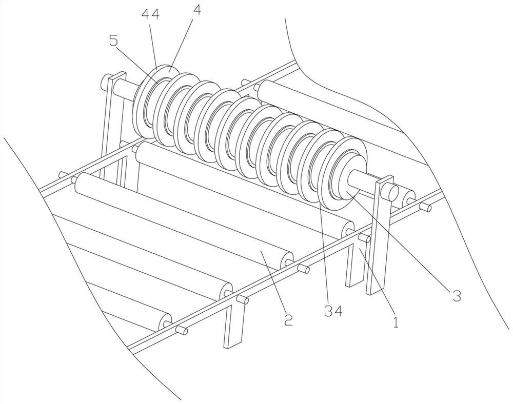
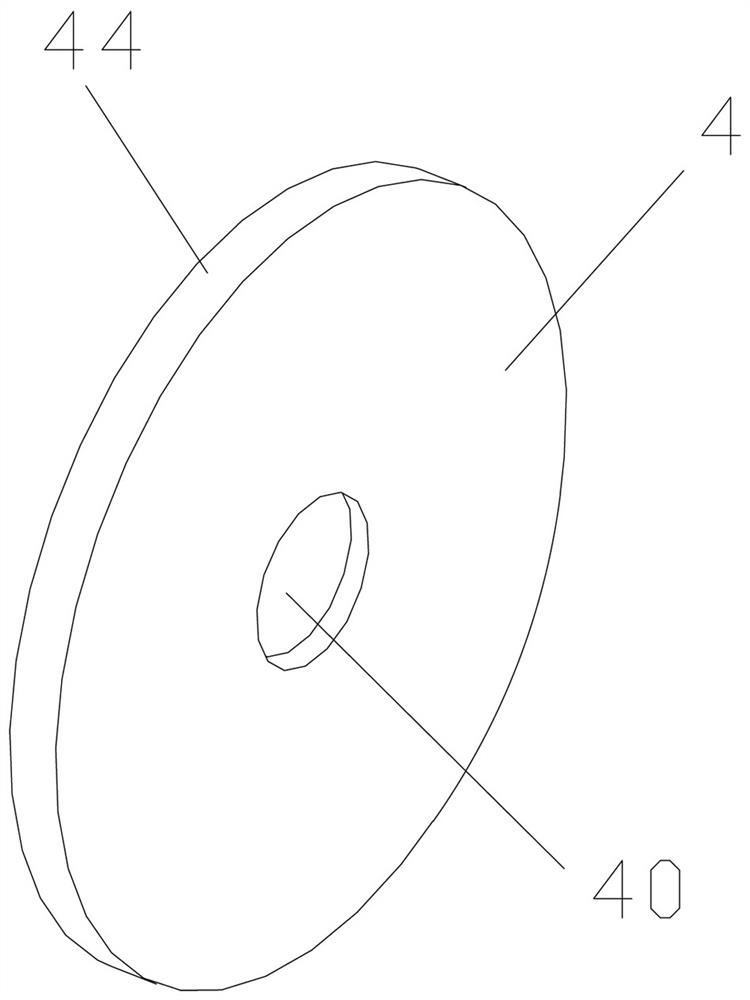
[0029] Example 1, such as Figure 1-10 As shown, a drying device for wood-plastic flooring includes a frame 1 and a conveying table 2 installed on the frame 1 for conveying wood-plastic flooring, and above the conveying table 2 is provided with a The heating body 3, the outer wall of the heating body 3 is sleeved with several heat dissipation and drying sets 4 distributed along the left and right directions of the heating body 3 and used to be close to the upper surface.

[0030] The direction of the conveying platform 2 is set as right rear and forward, that is, the rear end side of the conveying platform 2 is the upstream section, the front end side of the conveying platform 2 is the downstream end, and the two sides on the traveling path of the conveying platform 2 are used as the left and right sides. The heating body 3 can be installed and connected on the frame 1, and is set by the heat dissipation and drying sets 4 arranged at intervals, so that the heat of the heating ...

Embodiment 2

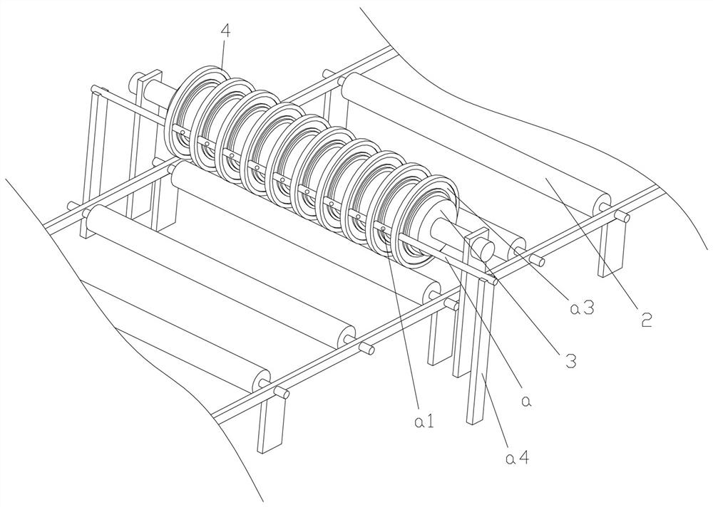
[0038] Embodiment 2, the drawings refer to Embodiment 1, a dust removal device for wood-plastic flooring, including a frame 1 and a heating body 3 installed on the frame 1, the heating body 3 is a heating roller, and the In the heating area of ​​the outer wall of the heating body 3 is provided an air outlet pipe a consistent with the left and right axial direction of the heating body 3 , and the air outlet pipe a has air outlets a1 arranged at intervals along the axial direction of the heating body 3 . In this embodiment, the structure of the drying device in Embodiment 1 can be used to remove dust while heating, so that the quality of subsequent embossing or wire drawing operations is better, and the impact of dust and other impurities on the quality of wood-plastic flooring products is reduced. The outer wall of the heating body 3 forms a heating area due to the presence of air, and the hot air can be blown to the wood-plastic floor for drying and heating through the air outl...

Embodiment 3

[0044] Embodiment 3, the drawings refer to Embodiment 1, a wood-plastic floor processing equipment, including a frame 1 and a conveying device for conveying the wood-plastic floor, the conveying device includes a frame mounted on the frame 1 A conveying platform 2 for conveying wood-plastic flooring, the conveying platform 2 carries a rectangular limit frame b for limiting the surroundings of the wood-plastic floor, and the frame 1 is respectively provided with a A row of guiding and limiting wheels 6 for limiting and guiding the left side and the right side of the rectangular limiting frame b. The rectangular limiting frame b can better limit the wood-plastic floor, so that the wood-plastic floor is not easy to shift, and can perform better drying, dust removal, wire drawing, embossing and other operations. Of course, the height of the rectangular limiting frame b is less than For the wood-plastic floor, the rectangular limiting frame material can be made of high temperature ...


PUM


Abstract

The invention relates to the technical field of wood-plastic floor production, in particular to a drying device for wood-plastic floors. The drying device comprises a machine frame, a conveying tableinstalled on the machine frame and used for conveying the wood-plastic floors, and a heating body extending in the left-right direction and arranged above the conveying table. The outer wall of the heating body is sleeved with a plurality of heat dissipation drying sleeve blocks which are distributed in the left-right direction of the heating body at intervals and used for being close to the uppersurface, and the heating and drying effect is good.

Description

technical field [0001] The invention relates to the technical field of wood-plastic floor production, in particular to a drying device for wood-plastic floor. Background technique [0002] Existing wood-plastic flooring is being used more and more, which puts forward higher requirements for the quality of wood-plastic flooring products. Many of the designed processes have a greater impact on wood-plastic flooring, such as for Heating and drying of wood-plastic flooring, etc., such as a heating device for floor production disclosed in a Chinese patent with application number 201811112763. The way of groove, electromagnet unit, lifting unit, current regulating unit and dustproof unit can achieve the effect of effective use of heating equipment. [0003] The existing heating equipment is not effective, it only simply heats and dries the board, in fact, it cannot be effectively combined with the subsequent process, especially the embossing or wire drawing of the wood-plastic fl...

Claims


Application Information

Patent Timeline
IPC IPC(8): F26B15/12F26B23/00F26B25/00E04F15/10
CPCF26B15/122F26B23/00F26B25/00E04F15/105
Inventor 吴晓雷陈建伟胡云海
Owner 浙江天博生物新材料股份有限公司
Why Eureka
Try Eureka