
Heat exchanger, heating water circulating unit and control method of heating water circulating unit

A technology for heat exchangers and hot water production, which is used in indirect heat exchangers, heat exchanger types, compressors with reversible cycles, etc. problems such as operating range, to achieve the effect of improving the applicable range of working conditions, eliminating frequent defrosting problems, and improving service life

Active Publication Date: 2021-02-26
GREE ELECTRIC APPLIANCES INC
View PDF3 Cites 0 Cited by
  • Summary
  • Abstract
  • Description
  • Claims
  • Application Information

AI Technical Summary

Problems solved by technology

[0007] Therefore, the technical problem to be solved in this disclosure is to overcome the high heat exchange performance fins of the heat exchangers in the prior art that are suitable for the normal temperature section, which cannot meet the requirements of the large temperature operating range of the multifunctional water heater and the small application range of the working conditions. defects, thereby providing a heat exchanger, a heating water circulation unit and a control method thereof

Method used


Image

  • Heat exchanger, heating water circulating unit and control method of heating water circulating unit
  • Heat exchanger, heating water circulating unit and control method of heating water circulating unit
  • Heat exchanger, heating water circulating unit and control method of heating water circulating unit

Examples


Embodiment Construction

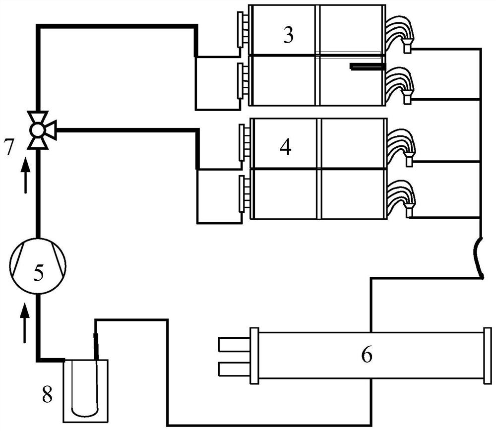
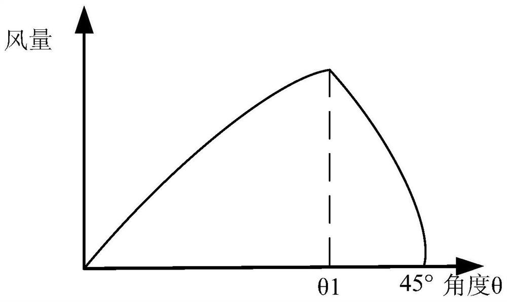
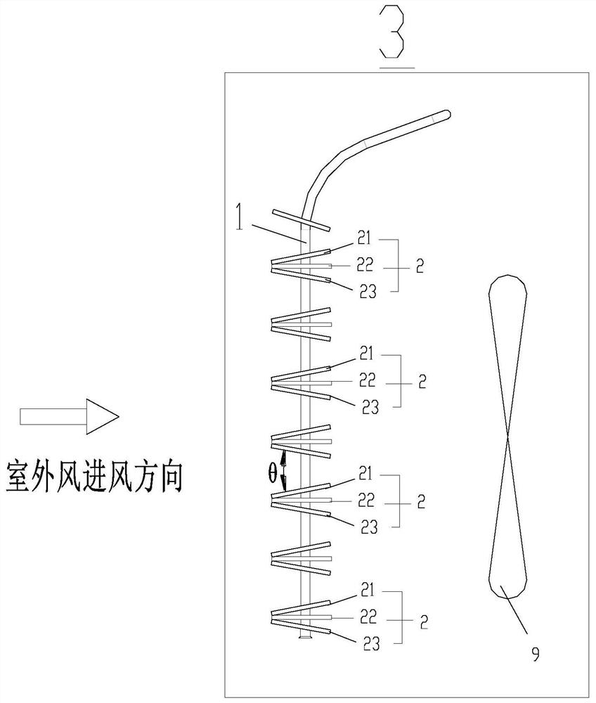
[0045] Such as Figure 1-3 As shown, the present disclosure provides a heat exchanger comprising:

[0046] Heat exchange tubes 1 and heat exchange fins 2, the heat exchange fins 2 are perforated on the heat exchange tubes 1, and the heat exchange fins 2 are at least two, at least two of the heat exchange fins The fins 2 form a group of heat exchange fins; and in two adjacent groups of heat exchange fins, the heat exchange fins in the first group of heat exchange fins that are close to the second group of heat exchange fins , and the heat exchange fins in the second group of heat exchange fin groups that are close to the first group of heat exchange fin groups gradually decrease along the direction of air flow, and the distance is perpendicular to the direction of air flow distance.

[0047] In the present disclosure, at least two heat exchanging fins are arranged as one heat exchanging fin group, and among two adjacent heat exchanging fin groups, the heat exchanging fin grou...


PUM


Abstract

The invention provides a heat exchanger, a heating water circulating unit and a control method of the heating water circulating unit. The heat exchanger comprises a heat exchange pipe and heat exchange fins, the heat exchange fins are arranged on the heat exchange pipe in a penetrating mode, the number of the heat exchange fins is at least two, and the at least two heat exchange fins form a heat exchange fin set; and in every two adjacent heat exchange fin sets, the distance between the heat exchange fin, close to the second heat exchange fin set, in the first heat exchange fin set and the heat exchange fin, close to the first heat exchange fin set, in the second heat exchange fin set is gradually decreased in an airflow flowing direction, and the distance is the distance perpendicular tothe airflow flowing direction. The distance between the fins can be gradually reduced in the airflow flowing direction, the large fin distance is formed, the air speed is increased, the air volume isincreased, the heat exchange capacity of the heat exchange fins is improved, the defrosting capacity is improved, the large-temperature operation range of a multifunctional water heater can be effectively met, and the working condition application range is widened.

Description

technical field [0001] The present disclosure relates to the technical field of air conditioning, and in particular to a heat exchanger, a hot water circulation unit and a control method thereof. Background technique [0002] The heating operating range of the multi-function water heater is generally 35~-35°C, but within the range of 35~-7°C, it will not enter the state of frequent defrosting and can run for a long time. However, there will be abnormal situations. For example, in the areas along the Yangtze River in China, the humidity is too high, and when the temperature is lower than 0°C, there will be a lot of frost. At this time, the defrosting load of the whole machine is very large, which will occupy a very large load output of the whole machine. And there will be problems such as unclean defrosting and frequent defrosting. [0003] From another point of view, when the external ambient temperature is -7~-35°C, there will be a lot of frost on the fins at this time, an...

Claims


Application Information

Patent Timeline
Patent Type & Authority Applications(China)
IPC IPC(8): F28D1/04F28F1/12F25B13/00F25B39/00F25B41/20F25B47/02F25B49/02
CPCF25B13/00F25B39/00F25B47/02F25B49/02F25B2313/02731F28D1/04F28F1/12
Inventor 罗攀黄嘉希崔润中胡乾龙郭锦
Owner GREE ELECTRIC APPLIANCES INC
Learn More