A large field of view wavefront measurement device and method, equipment and medium

A technology of wavefront measurement and large field of view, which is applied in measurement devices, measurement optics, optical radiation measurement, etc., can solve the problems of increasing the cost of testing, difficult to achieve wavefront measurement, etc., and achieve the effect of low cost

Active Publication Date: 2021-09-21
NAT UNIV OF DEFENSE TECH
View PDF5 Cites 0 Cited by
  • Summary
  • Abstract
  • Description
  • Claims
  • Application Information

AI Technical Summary

Problems solved by technology

[0004] On the one hand, the present invention provides a large field of view wavefront measurement device to solve the problem that the existing large field of view wavefront measurement requires a large-scale optical lens or concave mirror, which leads to a significant increase in the cost of the test and makes it difficult to achieve a larger field of view. Technical Problems of Wavefront Measurement

Method used


Image

  • A large field of view wavefront measurement device and method, equipment and medium
  • A large field of view wavefront measurement device and method, equipment and medium
  • A large field of view wavefront measurement device and method, equipment and medium

Examples


Embodiment Construction

[0035] It should be noted that, in the case of no conflict, the embodiments in the present application and the features in the embodiments can be combined with each other. The present invention will be described in detail below with reference to the accompanying drawings and examples.

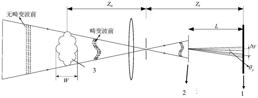
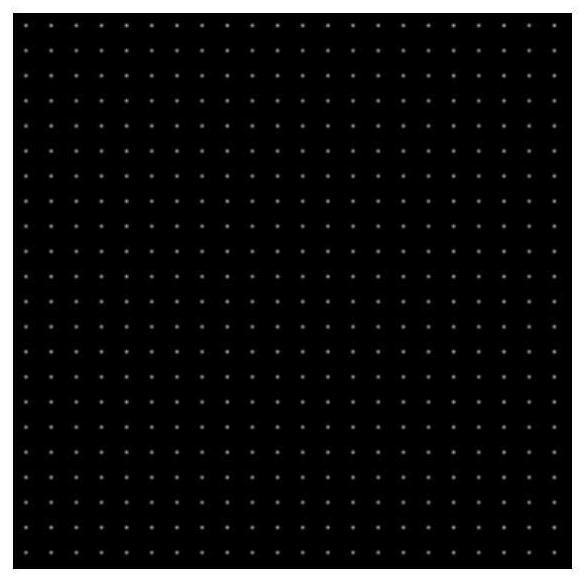
[0036] refer to figure 1 , a preferred embodiment of the present invention provides a large field of view wavefront measurement device, including an image sensor provided with an imaging target surface 1, a mask plate 2 is installed in front of the imaging target surface 1, and the mask A plurality of miniature light-through holes are evenly arranged on the plate 2 according to the preset distribution density, the diameter of the micro-light through-holes is d>10λ, and the diameter d and the distance between the mask plate 2 and the imaging target surface 1 satisfy the relationship: At the same time L>>25λ, where λ is the wavelength of light.

[0037] Considering that when the miniature clea...


PUM


Abstract

The invention discloses a large field of view wavefront measurement device, method, equipment and medium. The device includes an image sensor provided with an imaging target surface. A mask plate is installed in front of the imaging target surface. The mask A plurality of micro-light holes are evenly arranged on the membrane plate according to the preset distribution density. The diameter of the micro-holes is d>10λ, and the diameter d and the distance between the mask plate and the imaging target surface satisfy the relationship: at the same time L>>25λ, λ is the wavelength of light. The invention can make use of the imaging characteristics of ordinary converging lenses to realize wavefront measurement of large field of view at low cost. During the measurement, a mask plate with micro-holes with a set density is designed, combined with a cross-correlation calculation method, a breakthrough It eliminates the traditional wavefront test’s dependence on collimated light, and can achieve large-field wavefront measurement according to the different field angles of common lenses used. No additional large-size concave mirrors or lenses are required, and the cost is low.

Description

technical field [0001] The present invention relates to the technical field of wavefront measurement, in particular to a large field of view wavefront measurement device and method, equipment and medium. Background technique [0002] The earliest Hartmann wavefront sensor is mainly realized by arranging a Hartmann plate with many small holes in front of the imaging target surface. The light beam will form many small beams after passing through the Hartmann plate. The position of the beam on the target surface will change after being affected by the disturbance of the variable refractive index field. According to the Huygens principle combined with the distance between the Hartmann plate and the target surface, the spatial gradient of the wavefront at the corresponding small hole can be obtained, and an appropriate integral method is selected to complete the wavefront reconstruction. The Shack-Hartmann (S-H) wavefront sensor replaces the early Hartmann plate by using a micr...

Claims


Application Information

Patent Timeline
Patent Type & Authority Patents(China)
IPC IPC(8): G01J9/00
CPCG01J9/00G01J2009/002
Inventor 丁浩林易仕和
Owner NAT UNIV OF DEFENSE TECH
Why Eureka
Try Eureka