Sample preparation device and sample preparation method for expansive soil in liquid limit state
A technology of expansive soil and liquid limit, which is applied to the sample preparation device and the field of sample preparation under the liquid limit state of expansive soil, which can solve the problems of non-density of layer-to-layer connection, large dispersion of parallel test results, low shear strength of expansive soil, etc. question
- Summary
- Abstract
- Description
- Claims
- Application Information
AI Technical Summary
Problems solved by technology
Method used
Image
Examples
Embodiment 1
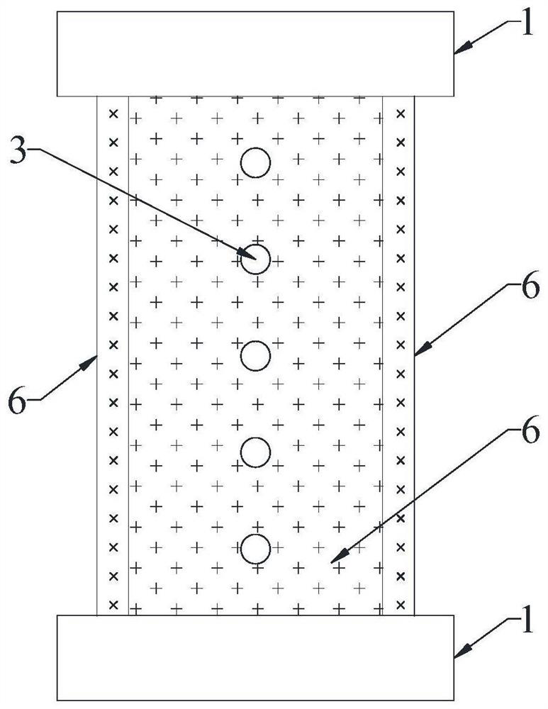
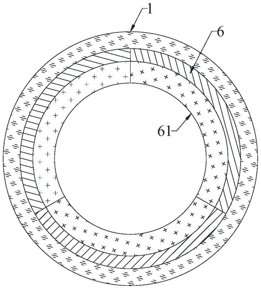
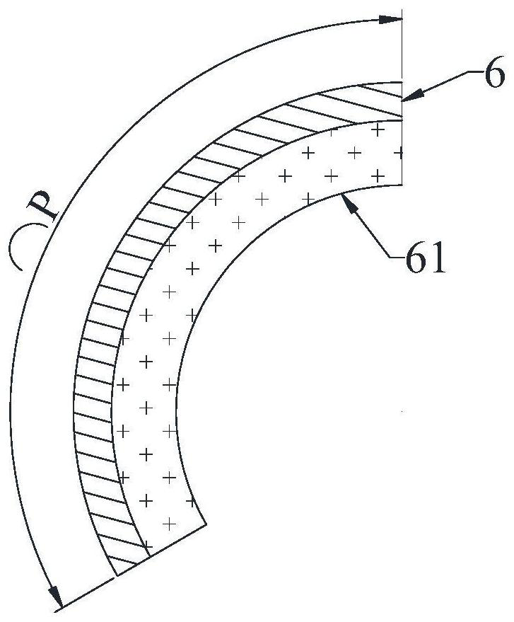
[0032] like Figure 1-3 As shown, the sample preparation device under the liquid limit state of the expansive soil includes a cylindrical sleeve, and the sleeve includes a plurality of side plates 6, the cross section of the side plates 6 is arc-shaped, and the side plates 6 The side wall of the side wall is provided with a plurality of drain holes 3, and the drain holes 3 are arranged at equal intervals along the length direction of the side plate 6, and the drain holes 3 are all arranged in the middle of the side plate 6; the upper and lower sides of the sleeve Both ends are sleeved with a collar 1, the inner wall of the collar 1 is provided with an internal thread, and the end of the side plate 6 is provided with an external thread 5 matching the internal thread.
[0033] In this embodiment, the number of side plates 6 is preferably three, and the three side plates 6 form a sleeve, such as figure 2 shown.
[0034] The three side plates 6 are connected to each other to fo...
Embodiment 2
[0039] like Figure 4-5 As shown, one side of the side plate 6 is provided with a rib 63, the cross section of the outer periphery of the rib 63 is arc-shaped, and the upper end of the rib 63 extends to the upper end surface of the side plate 6, and the rib 63 extends to the upper end surface of the side plate 6. The lower end of the 63 extends to the lower end surface of the side plate 6; the other side of the side plate 6 is provided with a slot 62 matching the rib 63, and the upper end of the slot 62 extends to the upper end surface of the side plate 6, The lower end of the locking slot 62 extends to the lower end surface of the side plate 6 .
[0040] First connect the two side plates 6 to each other, so that the ribs 63 are inserted into the corresponding slots 62; then insert the third side plate 6 between the two connected side plates 6, and insert the side plate 6 , it needs to be inserted from top to bottom, and the corresponding ribs 63 and the slots 62 are butted a...
Embodiment 3
[0042] like Figure 6-8As shown, the outer wall of the side plate 6 is provided with a limiting groove 64 arranged along the circumference of the side plate 6, one end of the limiting groove 64 extends to one side of the side plate 6, and the limiting groove 64 The other end of the other end extends to the other side of the side plate 6, and the clamping plate 2 is arranged in a clearance fit with the limiting groove 64 at the limiting groove 64, and the projection of the clamping plate 2 on the horizontal plane is an arc structure.
[0043] When the three side plates 6 are spliced together, in order to ensure that the external threads 5 at the ends of the three side plates 6 are spliced into a complete thread structure, the clamping plate 2 is first inserted into the first limiting groove 64. The bit grooves 64 are spliced into a circular groove structure. If the clamping plate 2 can smoothly rotate one circle along the circular groove, it means that the end faces of th...
PUM
 Abstract
Description
Claims
Application Information
 - R&D
- Intellectual Property
- Life Sciences
- Materials
- Tech Scout
- Unparalleled Data Quality
- Higher Quality Content
- 60% Fewer Hallucinations
Browse by: Latest US Patents, China's latest patents, Technical Efficacy Thesaurus, Application Domain, Technology Topic, Popular Technical Reports.
© 2025 PatSnap. All rights reserved.Legal|Privacy policy|Modern Slavery Act Transparency Statement|Sitemap|About US| Contact US: help@patsnap.com


