Optical fiber fixing device for photoelectric equipment and using method thereof

An optical fiber fixing device, optoelectronic equipment technology, applied in the direction of light guide, optics, optical components, etc., can solve the problems of unstable connection, fiber line falling off, etc., and achieve the effect of stable and convenient movement

Pending Publication Date: 2021-02-26
深圳新海讯光电有限公司
View PDF8 Cites 0 Cited by
  • Summary
  • Abstract
  • Description
  • Claims
  • Application Information

AI Technical Summary

Problems solved by technology

[0003] At present, the fixing method of the optical fiber of the optoelectronic equipment is relatively simple. The optical fiber is mainly connected to the optoelectronic equipment throug

Method used


Image

  • Optical fiber fixing device for photoelectric equipment and using method thereof
  • Optical fiber fixing device for photoelectric equipment and using method thereof
  • Optical fiber fixing device for photoelectric equipment and using method thereof

Examples


Example Embodiment

[0026]The technical solutions in the embodiments of the present invention will be clearly and completely described below in conjunction with the accompanying drawings in the embodiments of the present invention. Obviously, the described embodiments are only a part of the embodiments of the present invention, rather than all the embodiments. Based on the embodiments of the present invention, all other embodiments obtained by those of ordinary skill in the art without creative work shall fall within the protection scope of the present invention.
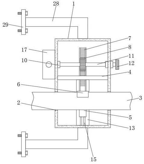
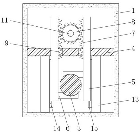
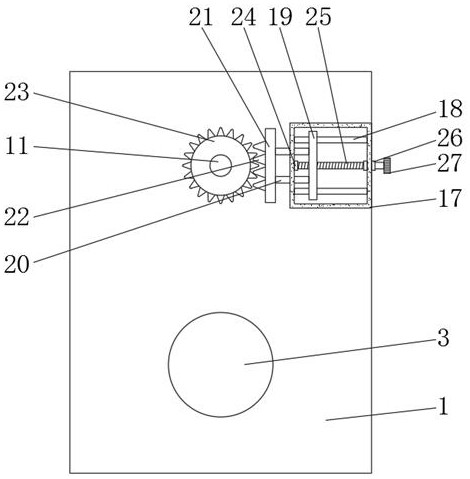
[0027]As attachedFigure 1-4The illustrated optical fiber fixing device for optoelectronic equipment includes a fixing box 1, and the bottom of both sides of the fixing box 1 is provided with through holes 2, and the inside of the through hole 2 is threaded with an optical fiber cable 3, and the inside of the fixing box 1 is fixed The partition 4 is connected, and the interior of the partition 4 is provided with two movable plates 5 distributed ...


PUM


Abstract

The invention discloses an optical fiber fixing device for photoelectric equipment and a using method of the optical fiber fixing device, and particularly relates to the field of photoelectric equipment, the optical fiber fixing device comprises a fixing box, through holes are formed in the bottoms of the two sides of the fixing box, optical fiber cables are arranged in the through holes in a penetrating mode, and a partition plate is fixedly connected in the fixing box; two movable plates which are distributed front and back are arranged in each partition plate in a penetrating mode, clampingplates are fixedly connected to the bottoms of the surfaces of the two movable plates, the two clamping plates are clamped on the upper side and the lower side of an optical fiber cable, and a plurality of gear teeth are fixedly connected to the opposite sides of the two movable plates. According to the invention, the power gear can be driven to rotate by utilizing the rotation of the handle, andthen the meshing connection between the power gear and the gear teeth on the surfaces of the movable plates is utilized, so that the rotation of the power gear drives the two movable plates to move relatively, and the relative movement of the two movable plates enables the two clamping plates to clamp and tighten an optical fiber cable; therefore, the effect of fixing the optical fiber cable is achieved.

Description

technical field [0001] The invention relates to the technical field of optoelectronic equipment, and more specifically, the invention relates to an optical fiber fixing device for optoelectronic equipment and a method for using the same. Background technique [0002] The optoelectronic industry is the sum of all kinds of parts, components, equipment and application markets composed of optoelectronic technology as the core. All commercial activities and equipment used in the optoelectronic industry are optoelectronic equipment. [0003] At present, the fixing method of the optical fiber of the optoelectronic equipment is relatively simple. The optical fiber is mainly connected to the optoelectronic equipment through the joint, but because the connection is not stable enough, the optical fiber line often falls off. Therefore, a fiber optic fixing device for optoelectronic equipment and How to use it. Contents of the invention [0004] In order to overcome the above-mention...

Claims


Application Information

Patent Timeline
IPC IPC(8): G02B6/42
CPCG02B6/424
Inventor 吴海平肖庆强
Owner 深圳新海讯光电有限公司
Why Eureka
Try Eureka