
Ticket card conveying mechanism of entrance ticket selling equipment

A technology of conveying mechanism and conveying mechanism, which is applied in ticketing equipment, ticket printing machines, transportation and packaging, etc. It can solve the problems of insufficient accuracy, overall equipment paralysis, jamming, etc., and achieve the effect of avoiding jamming

Inactive Publication Date: 2021-02-26
王野
View PDF0 Cites 1 Cited by
  • Summary
  • Abstract
  • Description
  • Claims
  • Application Information

AI Technical Summary

Problems solved by technology

[0003] The structure of the existing ticket removal mechanism is complicated, and often due to insufficient accuracy, it is difficult to remove the card or jam the card, resulting in the paralysis of the overall equipment and increasing the maintenance cost of the equipment, which is time-consuming and laborious

Method used


Image

  • Ticket card conveying mechanism of entrance ticket selling equipment
  • Ticket card conveying mechanism of entrance ticket selling equipment
  • Ticket card conveying mechanism of entrance ticket selling equipment

Examples


Embodiment 1

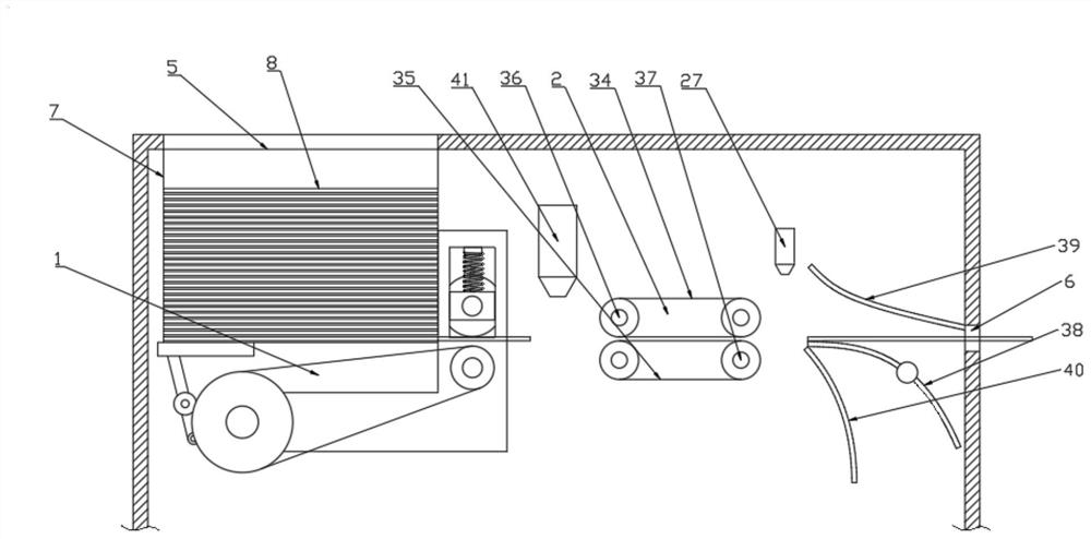
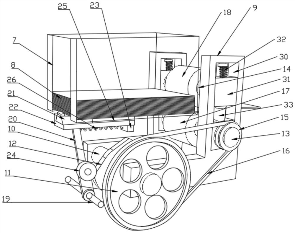
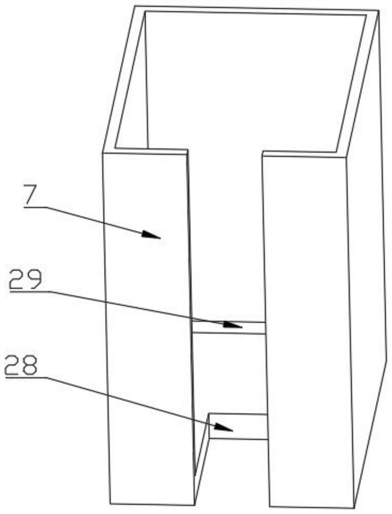
[0024] see Figure 1-5 , a ticket conveying mechanism for admission ticketing equipment, comprising a ticket take-out mechanism 1, a conveying mechanism 2, a diverting mechanism 3 and a reading and writing mechanism 4, and the ticket conveying mechanism 2, the turning mechanism and the reading and writing mechanism 4 are all set In the casing, the top of the casing is provided with a ticket card placement opening 5, the right side of the casing is provided with a ticket outlet 6, and the inside of the casing is provided with a ticket card box 7 at the position of the placement opening 5, and the ticket A plurality of ticket cards 8 are placed horizontally in the card box 7. The ticket card take-out mechanism 1 includes a base 9, a first rotating shaft 10, a first pulley 11, a rotating block 12, a second rotating shaft 13, a third rotating shaft 14, a Two belt pulleys 15, belts, driving roller 17, driven roller 18, the fourth rotating shaft 19, rotating rod 20, pushing block 21...

Embodiment 2

[0030] This embodiment has been improved on the basis of Embodiment 1, specifically:

[0031] The vertical plate of the base 9 is provided with a chute 30, the chute 30 is provided with a slide block 31, and the third rotating shaft 14 is rotated and arranged between the two slide blocks 31, and the top surface of the slide block 31 is in contact with the two slide blocks 31. A first spring 32 is provided between the chutes 30, and a top block 33 is provided between the bottom surface of the slide block 31 and the chute 30. By setting the slide block 31 and the first spring 32, when the ticket take-out mechanism 1 transports the ticket , the driving roller 17 and the driven roller 18 can carry out good frictional contact to the ticket card, under the premise of ensuring that the ticket card will not be bent and worn, the ticket card can be smoothly exported from the ticket guide port 29.

[0032] The working principle of the present invention is: after receiving the ticket car...


PUM


Abstract

The invention discloses a ticket card conveying mechanism of entrance ticket selling equipment, which comprises a ticket card taking-out mechanism, a conveying mechanism, a shunting mechanism and a read-write mechanism, and is characterized in that the ticket card taking-out mechanism is arranged to realize continuous conveying of a single ticket card, so that the phenomenon of blockage of the existing ticket card conveying mechanism is avoided; due to the arrangement of the conveying mechanism, the ticket cards are prevented from being bent and abraded in the conveying process; by arranging asliding block and a first spring, when the ticket card taking-out mechanism conveys the ticket card, a driving roller and a driven roller can be in good friction contact with the ticket card, and theticket card can be smoothly guided out of the ticket guide opening on the premise that it is guaranteed that the ticket card is not bent or abraded. Through arrangement of the shunting mechanism, theclassification processing of the ticket cards is realized.

Description

technical field [0001] The invention relates to the technical field of admission ticketing equipment, in particular to a ticket conveying mechanism of the admission ticketing equipment. Background technique [0002] At present, the ticket ticket card selling device is mainly composed of a ticket card take-out mechanism, a transmission mechanism, a ticket card reading and writing device, and a ticket card distribution device. In these links, the reliability of the ticket card take-out mechanism directly affects the entire process of ticket sales. [0003] The existing ticket card removal mechanism is complex in structure, often due to insufficient accuracy, it is difficult to remove the card or the card is jammed, resulting in the paralysis of the overall equipment and increasing the maintenance cost of the equipment, which is time-consuming and laborious. Contents of the invention [0004] The purpose of the present invention is to provide a ticket card conveying mechanism...

Claims


Application Information

Patent Timeline
Patent Type & Authority Applications(China)
IPC IPC(8): G07B1/00B65H1/06B65H3/24B65H5/06
CPCB65H1/06B65H3/242B65H5/062G07B1/00
Inventor 王野
Owner 王野
Learn More