
Low-pass filter

A low-pass filter and through-slot technology, applied in the field of filters, can solve the problems of difficult debugging, long training and debugging technicians, and high debugging costs, and achieve the effects of saving debugging costs, simple structure, and increasing suppression.

Pending Publication Date: 2021-02-26
MOBILE ANTENNA TECH SHENZHEN +5
View PDF0 Cites 0 Cited by
  • Summary
  • Abstract
  • Description
  • Claims
  • Application Information

AI Technical Summary

Problems solved by technology

The structural characteristics of the traditional metal cavity coaxial cavity filter determine that the filter needs to be debugged, and the debugging is difficult. It takes a long time to train and debug technicians, the cost of debugging is high, and it is greatly affected by human factors. The cavity filter cannot meet the technical requirements of small size, high power, low frequency and wide frequency band, low insertion loss, and no adjustment

Method used


Image

  • Low-pass filter
  • Low-pass filter
  • Low-pass filter

Examples


Embodiment Construction

[0022] In order to make the object, technical solution and advantages of the present invention clearer, the present invention will be further described in detail below in conjunction with the accompanying drawings and embodiments. It should be understood that the specific embodiments described here are only used to explain the present invention, not to limit the present invention.

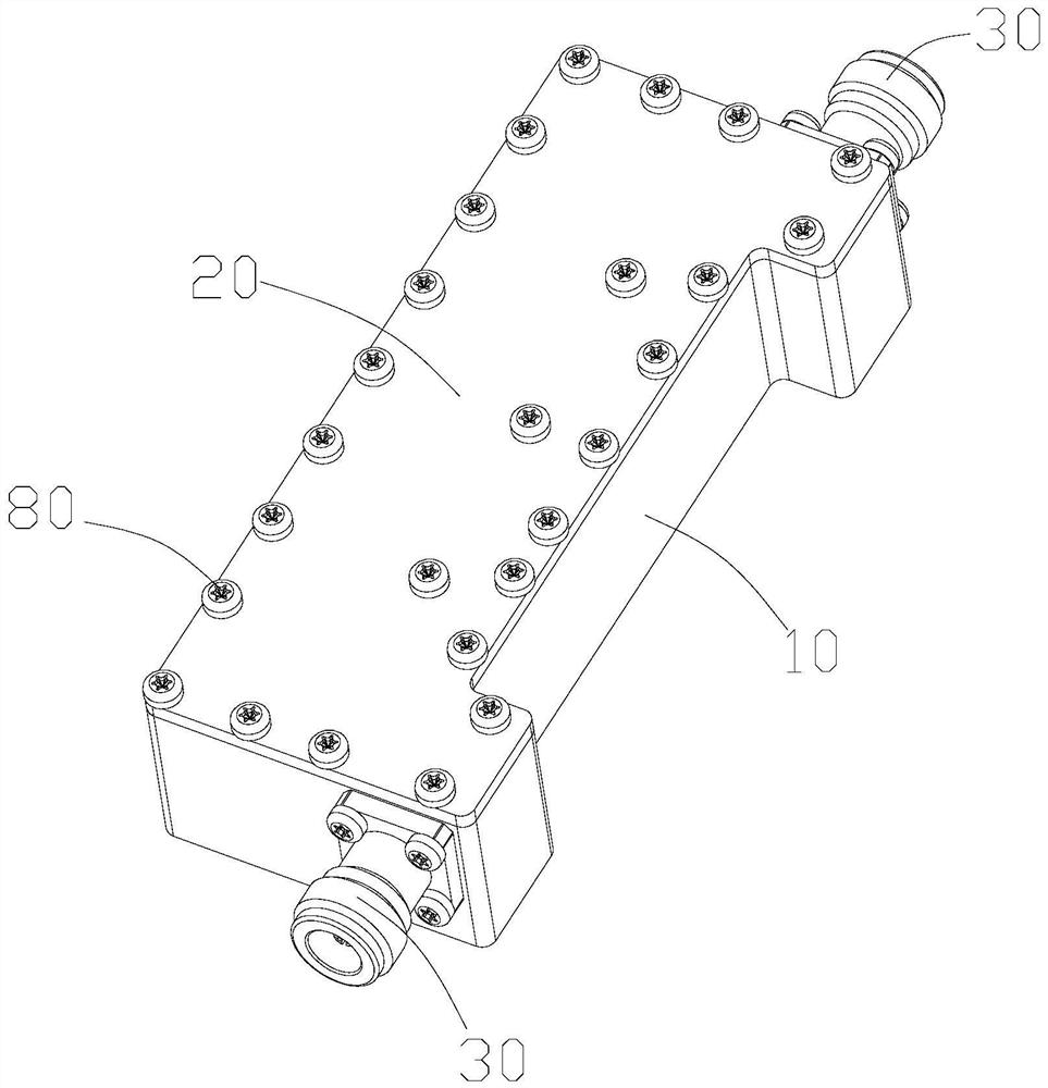
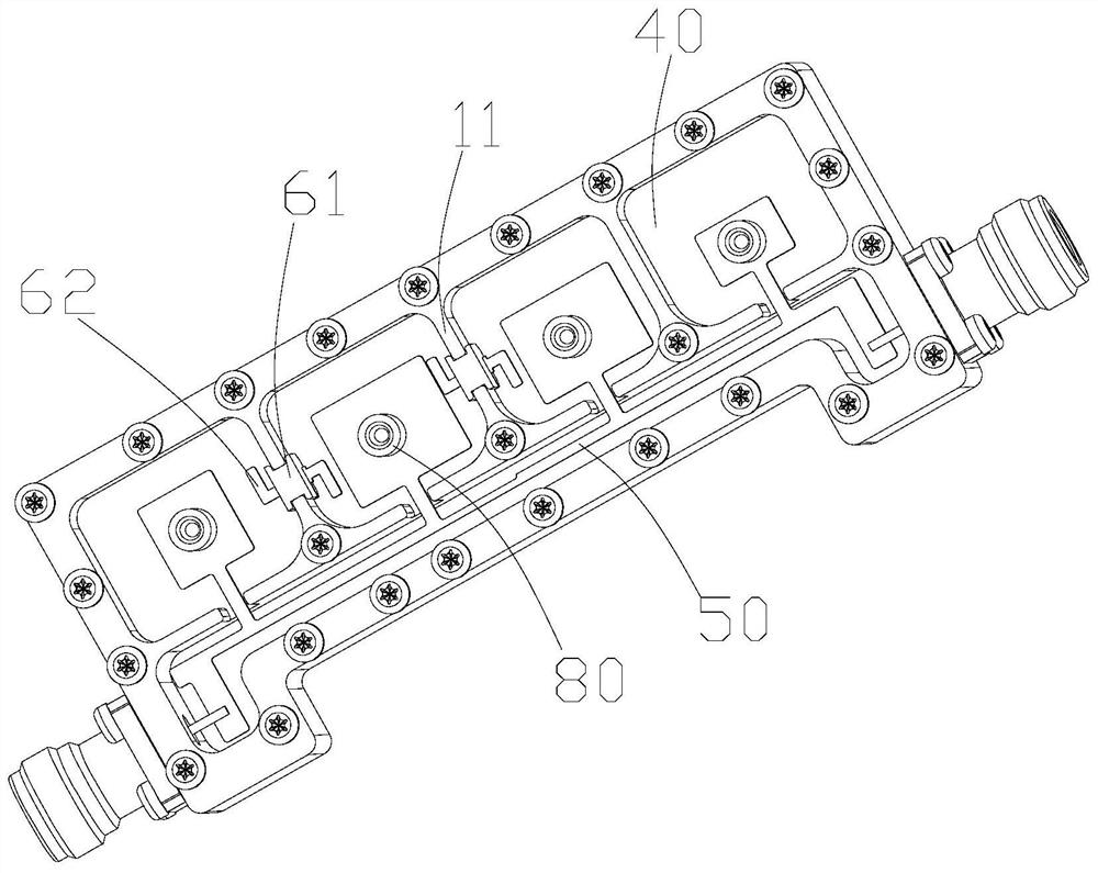
[0023] Such as Figure 1 to Figure 4 As shown, it is a low-pass filter provided by an embodiment of the present invention, including a housing 10, a cover plate 20, and a coaxial connector 30. A partition 11 is arranged inside the housing 10, and the partition 11 separates the inside of the housing 10. Separated into a plurality of cavities 40 , the cover plate 20 covers the plurality of cavities 40 , and the two ends of the housing 10 are respectively provided with coaxial connectors 30 . In this embodiment, the cover plate 20 is fixed on the top surface of the casing 10 by mounting screws 80 . ...


PUM


Abstract

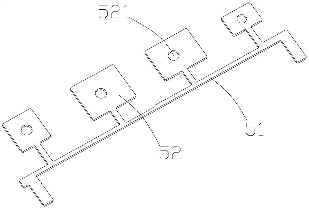
An embodiment of the invention provides a low-pass filter, belonging to the technical field of filters. The low-pass filter comprises a shell, a cover plate and coaxial connectors, wherein a partitionplate is arranged in the shell, and the interior of the shell is divided into a plurality of cavities by the partition plate; the cover plate covers the plurality of cavities; the coaxial connectorsare arranged at the two ends of the shell respectively; a strip line copper sheet is suspended in the shell and comprises a low-pass section used for suppressing harmonic waves and a plurality of copper sheet branches connected to the low-pass section and arranged at intervals, the two ends of the low-pass section are connected with the coaxial connectors at the two ends of the shell respectively,and the multiple copper sheet branches are correspondingly arranged in the multiple cavities respectively; and a coupling structure is arranged on the partition plate and comprises an insulating supporting body and a capacitor copper sheet fixed to the insulating supporting body, and the two ends of the capacitor copper sheet are located in the two cavities in the two sides respectively. According to the invention, the filter is small in size, low in frequency, wide in pass band, low in loss, high in power, free of debugging and capable of meeting the technical requirement for transmission zero points.

Description

technical field [0001] The invention belongs to the technical field of filters, in particular to a low-pass filter. Background technique [0002] The filter uses the characteristic that capacitive reactance or inductive reactance changes with frequency, and produces different responses to input signals of different frequencies, allowing signals of a specific frequency band to pass through smoothly, while suppressing signals of other frequencies. Filters are one of the most commonly used components in radio frequency circuits. Due to the different specific requirements of the application occasions, people often need to design different filters. The structural characteristics of the traditional metal cavity coaxial cavity filter determine that the filter needs to be debugged, and the debugging is difficult. It takes a long time to train and debug technicians, the cost of debugging is high, and it is greatly affected by human factors. The cavity filter cannot meet the technica...

Claims


Application Information

Patent Timeline
IPC IPC(8): H01P1/208H01P1/203H01P1/212
CPCH01P1/2039H01P1/208H01P1/212
Inventor 洪星谢龙成梁小健
Owner MOBILE ANTENNA TECH SHENZHEN
Learn More