A loudspeaker, and a voice coil driving system and driving method for the loudspeaker

A loudspeaker and voice coil technology, applied in the loudspeaker field, to achieve the effect of improving power efficiency

Active Publication Date: 2022-08-05
TYMPHANY ACOUSTIC TECH (HUIZHOU) CO LTD
View PDF8 Cites 0 Cited by
  • Summary
  • Abstract
  • Description
  • Claims
  • Application Information

AI Technical Summary

Problems solved by technology

[0005] The coil windings are partly placed in the air gap 3 of the magnetic circuit 2, which is where the region with the highest magnetic flux density resides, and when the coil windings are powered, they interact with the magnetic field of the magnetic circuit 2 to generate the sound for translating. The EMF of coil 1, however, is only actually provided by the voice coil 1 windings in the air gap 3 to reciprocate the substantial force of the voice coil 1, while the voice coil windings outside the air gap 3 do not contribute to the generation of significant EMF, these The winding is powered and in turn contributes to heating the voice coil, which becomes a major limiting factor in loudspeaker design

Method used


Image

  • A loudspeaker, and a voice coil driving system and driving method for the loudspeaker
  • A loudspeaker, and a voice coil driving system and driving method for the loudspeaker
  • A loudspeaker, and a voice coil driving system and driving method for the loudspeaker

Examples


Embodiment Construction

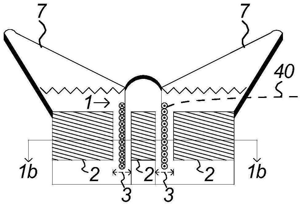
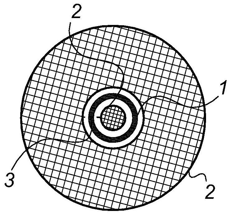
[0241] Figure 1a illustrates a cross-sectional view of an existing loudspeaker. Figure 1b illustrates a cross-sectional view at line 1b-1b in Figure 1a. In Figure 1a, disposed within the loudspeaker are two concentrically aligned magnetic components 2, which form a magnetic circuit. These magnetic members 2 are configured such that a circular air gap 3 is formed within the magnetic circuit 2 .

[0242] A voice coil 1 comprising a plurality of coil windings is further suspended within an air gap 3 . The windings of the voice coil 1 are configured such that when current is passed through the coil 1 , the electromotive force will move the voice coil 1 in the air gap 3 , actuating the diaphragm or diaphragm 7 . Therefore, the alternating current causes the reciprocating motion of the diaphragm 7, thereby generating the sound signal.

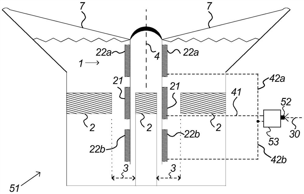
[0243] refer to figure 2 , the voice coil drive system 51 according to the embodiment of the present invention is shown. The voice coil drive s...


PUM


Abstract

A method for driving a voice coil of a loudspeaker may include providing a magnetic circuit with an air gap, providing a voice coil suspended in the air gap, and applying an audio signal to the voice coil to move the voice coil along an axis of travel. The voice coil, the voice coil includes a main voice coil segment and a pair of auxiliary voice coil segments arranged along the travel axis, and the voice coil segments in the pair of auxiliary voice coil segments are respectively arranged on the main voice coil either side of the segment, applying an audio signal includes continuously coupling a main drive signal to the main voice coil segment based on the audio signal and selectively coupling an auxiliary drive signal to the pair of auxiliary voice coil segments based on the audio signal, The disclosed embodiments further relate to voice coil drive systems and speakers including the voice coil drive systems.

Description

[0001] Cross-referencing of applications [0002] This application claims priority to US Provisional Application No. 62 / 890,962, filed August 23, 2019, which is incorporated herein by reference in its entirety. technical field [0003] The present application relates generally to loudspeakers, and more particularly, to voice coil arrangements, voice coil drive systems for loudspeakers, and methods of driving voice coils for loudspeakers for improved power handling and reduced electrical losses in driving electronic components. Background technique [0004] Referring to the prior art loudspeaker 50 illustrated in FIGS. 1a-1b, the loudspeaker 50 configured with the voice coil 1 includes a plurality of coil windings, which are powered by a drive power source, so that the voice coil 1 reciprocally actuates to produce acoustic audio the diaphragm 7. [0005] The coil winding is partially placed in the air gap 3 of the magnetic circuit 2, which is the area with the highest magnet...

Claims


Application Information

Patent Timeline
Patent Type & Authority Patents(China)
IPC IPC(8): H04R9/06H04R9/02H04R9/04
CPCH04R9/06H04R9/027H04R9/04H04R2209/00H03F3/181H03F2200/03H03G3/3005H03G3/04H03G5/16H04R2209/041H04R7/12H04R9/025H04R9/046H04R9/045H04R9/02G10L25/21G10L25/51H03G3/301H03G2201/103H04R3/00H04R29/003
Inventor 不公告发明人
Owner TYMPHANY ACOUSTIC TECH (HUIZHOU) CO LTD
Why Eureka
Try Eureka