Anti-flash single-live-wire power-taking wall switch circuit
A technology of wall switch and single fire, which is applied in the direction of battery circuit devices, circuit devices, AC network circuits, etc., can solve the problems of insufficient control methods of smart wall switches and the inability of users to choose arbitrarily, so as to prevent flickering, improve efficiency, The effect of simplifying the circuit structure
- Summary
- Abstract
- Description
- Claims
- Application Information
AI Technical Summary
Problems solved by technology
Method used
Image

Examples
Embodiment 1
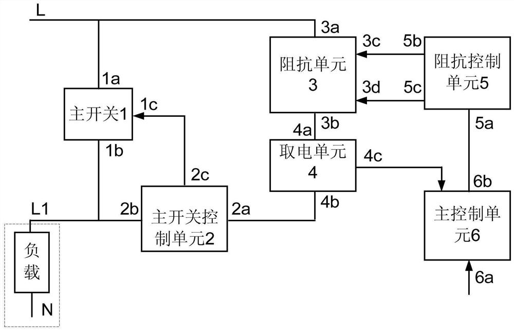
[0029] like figure 1As shown, a wall switch circuit for anti-flash single-fire power supply includes a main switch 1 arranged between the live wire L and the lamp wire L1 and connected to control the power on and off of the load. The impedance unit 3 for controlling the impedance, the power taking unit 4 for power taking and output power supply, the main switch control unit 2 for controlling the power on and off of the main switch 1, and the power taking unit 4 are connected in series. The main control unit 6 supplies power, and the main control unit 6 instructs the input terminal 6a to drive the impedance control unit 5 to control the impedance unit 3 to reduce the impedance after receiving the work instruction, so as to increase the flow current of the main switch control unit 2 and control the main switch 1 to turn on.
[0030] like figure 1 As shown, the 3a terminal of the impedance unit 3 is connected to the fire wire L and the 1a terminal of the main switch 1, the 3b te...
Embodiment 2
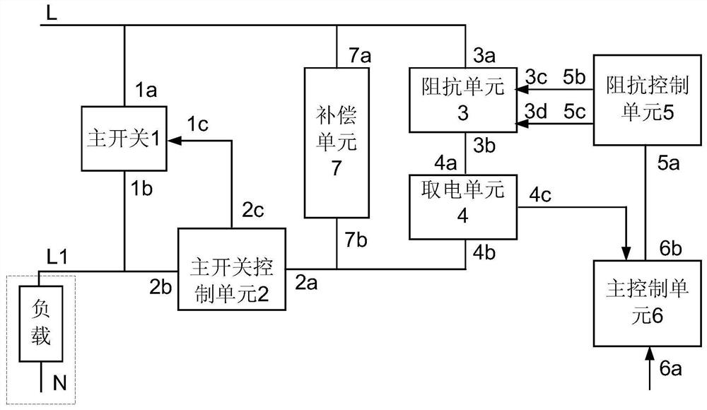
[0035] like figure 2 As shown, the impedance unit 3 and the power-taking unit 4 connected in series are connected in parallel with a compensation unit 7 for compensating the reactive current of the impedance unit 3.
[0036] like figure 2 As shown, the difference between the second embodiment of the circuit principle of the present invention and the first embodiment is that a compensation unit 7 is added, the 7a end of the compensation unit 7 is connected to the 3a end of the impedance unit 3, and the 7b end is connected to the 4b end of the power-taking unit 4, and the impedance The series circuit composed of the unit 3 and the power-taking unit 4 is connected in parallel to compensate the reactive current of the impedance unit 3. When the circuit resonates, the current flowing into the main switch control unit 2 and the load is greatly reduced compared with the implementation 1, thereby further preventing flicker and Slightly bright.
[0037] In order to explain the func...
Embodiment 3
[0055] like Figure 8 As shown, there is a manual switch K1 between the main switch 1, the electrical connection end of the impedance unit 3 and the live wire L, and a manual switch K2 is connected between the live wire L and the light wire L1; the command input terminal 6a of the main control unit 6 is connected with a sensing unit 8. Remote control unit 9 or remote control unit 10 .
[0056] like Figure 8 As shown, the difference between Embodiment 3 and Embodiment 2 of the circuit principle block diagram of the present invention is that a manual switch K1 is provided between the live wire L and the lamp wire L1, and the connection point between the live wire L and the manual switch K1 is connected to the 1a end of the main switch 1 and A manual switch K2 is provided between the connection points of terminal 7a of the compensation unit 7 . When you want to manually close the wall switch, you only need to manually close the manual switch K1. When you need to intelligently ...
PUM
 Abstract
Description
Claims
Application Information
 - R&D Engineer
- R&D Manager
- IP Professional
- Industry Leading Data Capabilities
- Powerful AI technology
- Patent DNA Extraction
Browse by: Latest US Patents, China's latest patents, Technical Efficacy Thesaurus, Application Domain, Technology Topic.
© 2024 PatSnap. All rights reserved.Legal|Privacy policy|Modern Slavery Act Transparency Statement|Sitemap