
Indoor design drawing worktable

A technology for interior design and work tables, applied in the field of furniture, can solve problems such as interference with the drawing process, reduced synchronous work efficiency, and cervical spine load loss

Pending Publication Date: 2021-03-02
WUHAN POLYTECHNIC
View PDF0 Cites 0 Cited by
  • Summary
  • Abstract
  • Description
  • Claims
  • Application Information

AI Technical Summary

Problems solved by technology

[0004] Aiming at the deficiencies in the prior art, the object of the present invention is to provide an interior design drawing work table to solve the problem that the interior design drawing work table will cause a large gap in the distance between the subsequent racks due to the intersecting jamming of the expansion angle in the adjustment of the lifting angle of the work table for interior design drawing, thereby Affects the corresponding curvature of the cervical spine, resulting in loss of cervical load on the verticality of the subsequent line of sight to the work table, causing the parallel lifting angle of the cervical spine to be affected by the drawing on the board, reducing the efficiency of synchronous work, and interfering with the drawing process.

Method used


Image

  • Indoor design drawing worktable
  • Indoor design drawing worktable
  • Indoor design drawing worktable

Examples


Embodiment 1

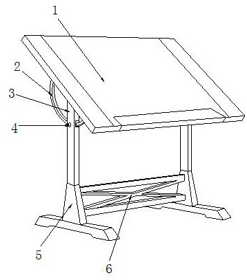
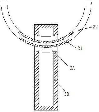
[0035] see Figure 1-Figure 8 , the present invention provides interior design drawing work table, its structure comprises: work desktop board 1, curved rail slide bar 2, wheel pad sliding bracket groove 3, button wheel cap 4, base support 5, truss frame 6, described wheel pad The sliding column groove 3 is inserted on the top of the base bracket 5 and is on the same vertical plane, the curved rail slide bar 2 is mechanically connected with the wheel pad sliding column groove 3, and the work table board 1 is nested in the curved rail. On the top of the rail slide bar 2 and perpendicular to each other, the button wheel cap 4 is mechanically connected to the wheel pad slip bracket slot 3, the base bracket 5 is welded to the truss frame 6 and is perpendicular to each other, the wheel pad slip bracket The column groove 3 is provided with an arc rail groove disk base 3A, a slide bracket pad rail groove 3B, a torsion spring pole 3C, and a pillar groove block 3D, and the arc rail gro...

Embodiment 2

[0043] see Figure 1-Figure 8 , the present invention provides interior design drawing work table, other respects are identical with embodiment 1, and difference is:

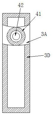
[0044] see image 3 , the button wheel cap 4 is composed of a clamping wheel ring 41 and a wheel cap body 42. The clamping wheel ring 41 is installed on the rear side of the wheel cap body 42 and the axis is collinear. The clamping wheel ring 41 and the The wheel cap body 42 is nested in one body, and the operating effect of a knob tightening is formed on the rear side of the wheel cap body 42 by clamping the wheel ring 41 .

[0045] see Image 6 , the clamping wheel ring 41 is composed of a lock pin fan plate 411 and a wheel ring groove 412. The lock pin fan plate 411 is installed inside the wheel ring groove 412 and is on the same vertical plane. The lock pin fan plate 411 and the wheel ring groove 412 adopt an interference fit, and the lock pin fan plate 411 is a plate structure with a convex pin block at ...


PUM


Abstract

The invention discloses an indoor design drawing worktable which structurally comprises a worktable top plate, a bent rail sliding rod, a wheel pad sliding support column groove, a button wheel cap, abase support and a truss frame, the bent rail sliding rod is matched with the wheel pad sliding support column groove, and an arc rail groove disc seat is erected at a bent rail rod to achieve the protractor type clamping shaft fine adjustment effect, it is guaranteed that the cervical vertebra lifting angle is aligned to a drawing working table top under the operation effect of alignment comfort, it is guaranteed that the sight line is perpendicular, cervical vertebra loads are relaxed, excessive bowing is avoided, the angle fine adjustment operation effect of 180-degree adjustment is improved, and the interval buckling phenomenon is improved; a sliding support pad rail groove sliding support pad protection machine frame is lifted to achieve the overall drawing auxiliary promotion effect, and the comfort of indoor design makers is guaranteed.

Description

technical field [0001] The invention is an interior design drawing work table, which belongs to the field of furniture. Background technique [0002] Interior design drawing is also called engineering drawing. It is to cooperate with the interior frame of the building to form an overlooking design drawing. The size of the drawing is adjusted in proportion to the actual needs, so as to improve the accuracy of the overall interior design engineering quantity and the effect of convenient operation. Currently, the technology is public The disadvantages to be optimized are: [0003] In the adjustment of the lifting angle of the work table for interior design and drawing, the distance between the subsequent racks will be large due to the cross jamming of the expansion angle, which will affect the corresponding curvature of the cervical spine, resulting in the cervical spine load on the verticality of the subsequent line of sight to the work table. Loss, the parallel lifting angle...

Claims


Application Information

Patent Timeline
Patent Type & Authority Applications(China)
IPC IPC(8): A47B27/02
CPCA47B27/02
Inventor 夏莲
Owner WUHAN POLYTECHNIC
Learn More