TBM tunnel multifunctional wet dust removal equipment
A wet dust removal and multi-functional technology, applied in the direction of dispersed particle separation, chemical instruments and methods, and the use of liquid separation agents, can solve the problems of difficult and fast discharge of dust, being wet by water mist, and affecting the construction progress, etc. The effect of human supervision, high degree of automation, and avoiding waste of resources
- Summary
- Abstract
- Description
- Claims
- Application Information
AI Technical Summary
Problems solved by technology
Method used
Image
Examples
Embodiment 1
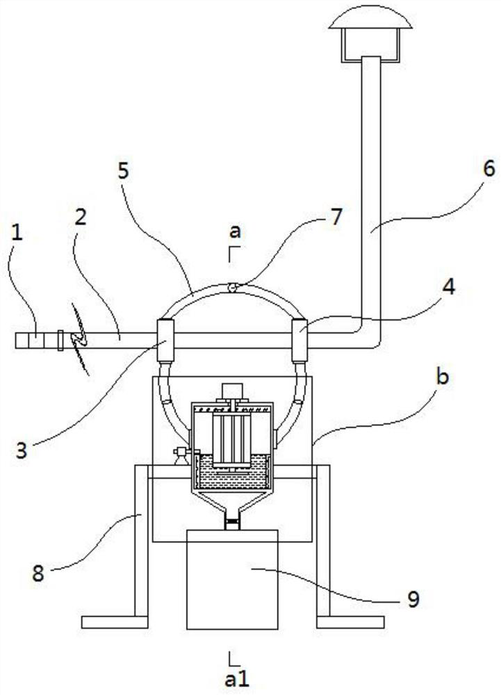
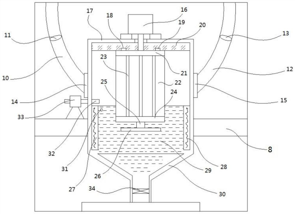
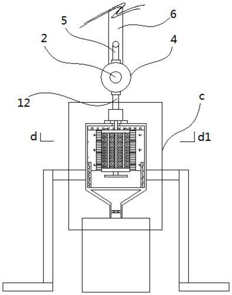
[0024] Such as Figure 1~5 Shown:
[0025] A TBM tunnel multifunctional wet dust removal equipment, including a dust removal fan 1, a connecting pipe 2, a chimney 6, and a wet dust removal device, the air outlet of the dust removal fan is connected to the left end of the connecting pipe 2, and the right end of the connecting pipe 2 Connected to the bottom of the chimney 6, the wet dust removal equipment includes a cylindrical housing 17, a motor 16 located at the top of the housing 17, a filter mechanism located in the housing, a water supply device, a heating device, a circulating dust removal device, And the settlement recovery device, the output shaft of the motor 16 penetrates the top of the housing 17 and is fixedly connected with the top of the filter mechanism, the lower part of the housing is provided with a water injection chamber 29, and the heating device includes a surrounding water injection The warehouse 29 and the annular wall 27 integrally formed with the inne...
Embodiment 2
[0028] On the basis of Embodiment 1, this embodiment has made further improvements, specifically:
[0029] Such as figure 2 , 4 As shown, the filter screen mechanism includes a circular top plate 21 and a bottom plate 24, and a connecting column 23 connected between the edge of the lower surface of the top plate 21 and the edge of the upper surface of the bottom plate 24. There are multiple connecting columns 23, and Together with the top plate 21 and the bottom plate 24, the cylindrical skeleton of the filter screen mechanism is formed. The outer side of the cylindrical skeleton is fixed with a filter screen 22, and the center of the upper end surface of the top plate 21 is fixedly connected with the output shaft of the motor 16. The output shaft, the top plate 21, the bottom plate 24, and the housing 17 are coaxial, and the lower end of the cylindrical skeleton extends into the water injection chamber 29.
[0030]In this embodiment, the filter screen mechanism rotates con...
Embodiment 3
[0032] On the basis of Embodiment 2, this embodiment has made further improvements, specifically:
[0033] Such as figure 2 As shown, the top in the housing 17 is also provided with a circular plate 20, the lower end surface of the circular plate 20 is provided with a circular chute 18, and the upper end surface of the top plate 21 is provided with a slider 19, The slider 19 is slidably connected with the circular chute 18 , and the circular chute 18 is coaxial with the housing 17 .
[0034] By arranging the circular chute 18, the rotation of the screen mechanism can be made more stable.
PUM
 Abstract
Description
Claims
Application Information
 - R&D
- Intellectual Property
- Life Sciences
- Materials
- Tech Scout
- Unparalleled Data Quality
- Higher Quality Content
- 60% Fewer Hallucinations
Browse by: Latest US Patents, China's latest patents, Technical Efficacy Thesaurus, Application Domain, Technology Topic, Popular Technical Reports.
© 2025 PatSnap. All rights reserved.Legal|Privacy policy|Modern Slavery Act Transparency Statement|Sitemap|About US| Contact US: help@patsnap.com


