Beverage bottle inner wall rapid cleaning equipment

A technology for cleaning equipment and beverage bottles, which is applied to the field of rapid cleaning equipment for the inner wall of beverage bottles, can solve the problems of low work efficiency, cumbersome operation, laborious and other problems, and achieves the effect of convenient operation and high work efficiency

Pending Publication Date: 2021-03-02
林超辉
View PDF6 Cites 3 Cited by
  • Summary
  • Abstract
  • Description
  • Claims
  • Application Information

AI Technical Summary

Problems solved by technology

[0005] In order to overcome the disadvantages of constantly moving the cleaning tool to clean the inner wall of the beverage bottle, the operation is cumbersome and laborious, and people can only clean the inner wall of one beverage bottle at a time, resulting in low work efficiency. The technical problem to be solved is to provide a Instead of manually cleaning the inner wall of the beverage bottle, it is easy to operate and labor-saving, and can clean the inner wall of four beverage bottles at one time. It is a quick cleaning equipment for the inner wall of beverage bottles with high work efficiency.

Method used


Image

  • Beverage bottle inner wall rapid cleaning equipment
  • Beverage bottle inner wall rapid cleaning equipment
  • Beverage bottle inner wall rapid cleaning equipment

Examples


Embodiment 1

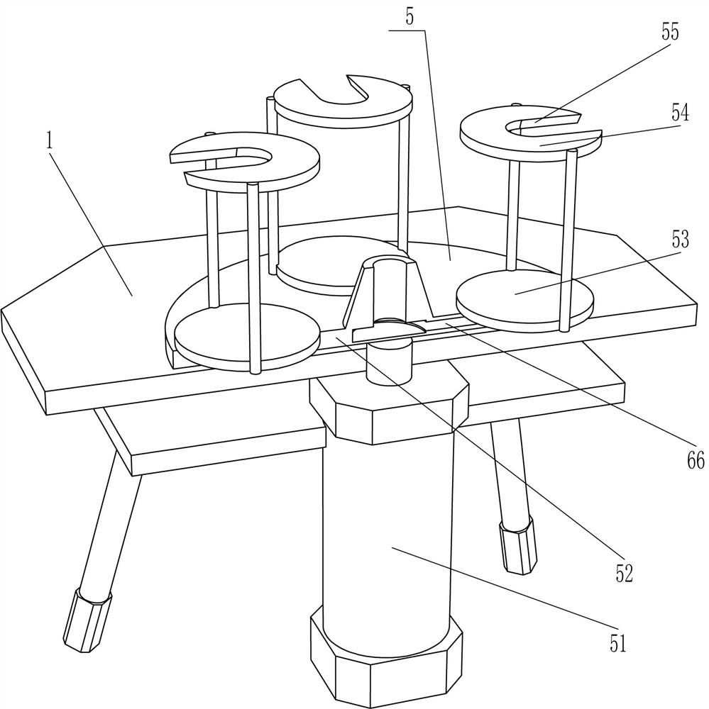
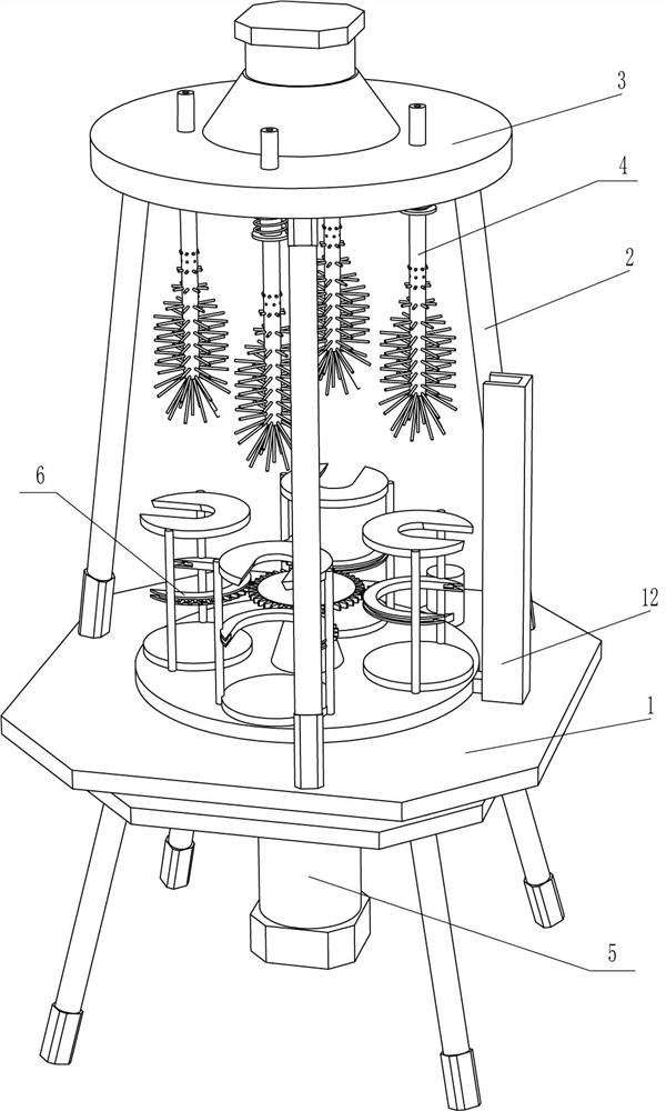
[0026] A quick cleaning device for the inner wall of a beverage bottle, such as figure 1 , figure 2 , image 3 and Figure 6 As shown, it includes a double-layer fixed frame 1, a support rod 2, an installation frame 3, a cleaning mechanism 4, and a pushing mechanism 5. The top of the double-layer fixed frame 1 is fixedly connected with three support rods 2 evenly spaced around the circumference, and the three support rods 2 An installation frame 3 is fixedly connected between the top ends, a cleaning mechanism 4 is provided in the installation frame 3, and a pushing mechanism 5 is provided on the double-layer fixed frame 1.

[0027] The cleaning mechanism 4 includes a motor 41, a first gear 42, a brush hollow rod 43 and a second gear 44, and the evenly spaced rotating type between the upper and lower sides of the installation frame 3 is connected with a brush hollow rod 43, and the brush hollow rod 43 has water outlet holes 45 evenly spaced in the middle circumferential di...

Embodiment 2

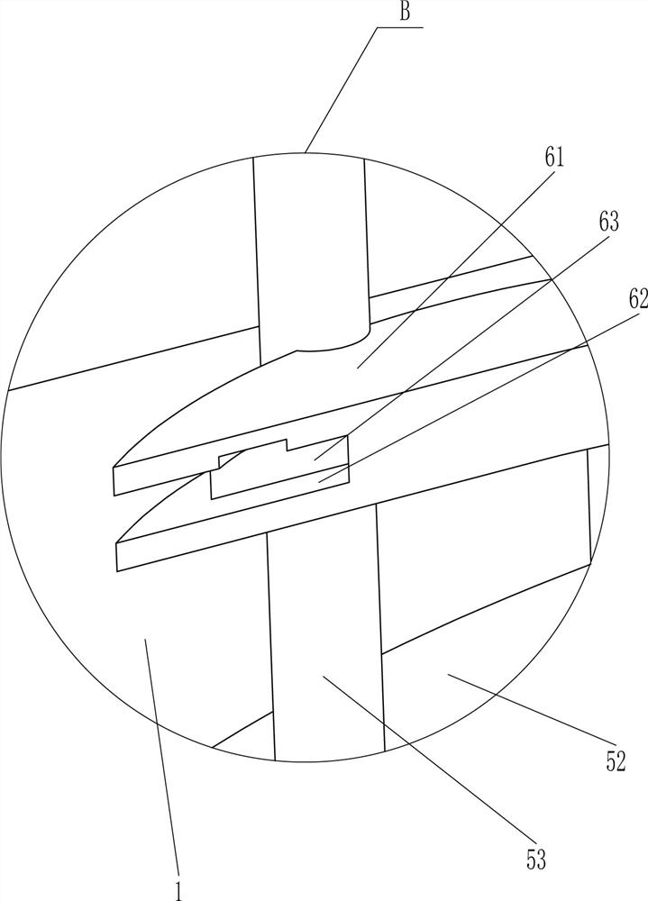
[0033] On the basis of Example 1, such as figure 1 , Figure 4 and Figure 7As shown, a locking mechanism 6 is also included. The locking mechanism 6 includes a c-shaped locking ring 61, an arc-shaped rack 63, a rotating shaft 64, a third gear 65 and a toggle lever 67. Connected with a rotating shaft 64, the top of the rotating shaft 64 is fixedly connected with a third gear 65, the outer surface of the mounting plate 52 is provided with a chute 66 toward the rear side, the bottom end of the rotating shaft 64 is fixedly connected with a toggle lever 67, and the tail end of the toggle lever 67 is located at Outside the chute 66, the toggle lever 67 is slidably matched with the chute 66, and a c-type lock ring 61 is fixedly connected between the middle part of the both sides of the discharge rack 53, and the outer surface of the c-type lock ring 61 is circumferentially provided with a guide groove 62, and the guide groove 62 The inner sliding type is provided with an arc-shape...

Embodiment 3

[0036] On the basis of embodiment 1 and embodiment 2, such as Figure 4 and Figure 5 As shown, it also includes a valve core 8, a compression spring 9 and a transmission ring sleeve 10. There is a special-shaped cavity 7 on the upper circumference of the brush hollow rod 43, and a sliding valve core 8 is provided in the special-shaped cavity 7. The two ends of the valve core 8 are located at Outside the special-shaped cavity 7, the valve core 8 cooperates with the inner side of the brush hollow rod 43, and the outer upper part of the brush hollow rod 43 is circumferentially slidingly provided with a transmission ring sleeve 10, and the top of the transmission ring sleeve 10 is fixedly connected with the outer two ends of the valve core 8 A compression spring 9 is fixedly connected to the inner bottom of the transmission ring sleeve 10, and the tail end of the compression spring 9 contacts and cooperates with the outer bottom of the installation frame 3.

[0037] Also include...


PUM


Abstract

The invention relates to cleaning equipment, in particular to beverage bottle inner wall rapid cleaning equipment. The technical aim to be achieved is how to design the beverage bottle inner wall rapid cleaning equipment. The equipment can replace manual work to clean the inner walls of beverage bottles, is convenient to operate and labor-saving, can clean the inner walls of the four beverage bottles at a time and is high in working efficiency. The beverage bottle inner wall rapid cleaning equipment comprises a double-layer fixing frame, and four supporting rods are fixedly connected to one side of the double-layer fixing frame at intervals. The four beverage bottles are placed on putting frames, an air cylinder is started, a mounting disc can drive the beverage bottles to move upwards through the putting frames to sleeve brush hollow rods, the air cylinder is stopped, a motor is started, the brush hollow rods can rotate to clean the inner walls of the beverage bottles through water, therefore people do not need to clean the inner walls of the beverage bottles manually, labor is saved, operation is convenient, and working efficiency is high.

Description

technical field [0001] The invention relates to a cleaning device, in particular to a fast cleaning device for the inner wall of a beverage bottle. Background technique [0002] Bottles and containers generally have a small mouth, a thin neck and a large belly, and are mostly made of plastic, porcelain or glass. It is often used to hold liquid substances (such as water, oil, etc.), and there are beverage bottles in the bottle. After the beverage bottle is recycled, the inner wall of the beverage bottle needs to be cleaned to facilitate subsequent processing. [0003] At present, most people clean the inner wall of the beverage bottle manually. First, people pour an appropriate amount of water into the beverage bottle, then insert the cleaning tool into the beverage bottle, and continuously move the cleaning tool to clean the inner wall of the beverage bottle. Such an operation is cumbersome and laborious, and people can only clean the inner wall of one beverage bottle at a ...

Claims


Application Information

Patent Timeline
Patent Type & Authority Applications(China)
IPC IPC(8): B08B9/36
CPCB08B9/36
Inventor 林超辉
Owner 林超辉
Why Eureka
Try Eureka