Feeding and discharging machine for cross cut shear line

A technology of cutting line and feeding machine, which is applied in the direction of shearing device, the accessory device of the shearing machine, metal processing equipment, etc., which can solve the problems of potential safety hazards, easy accidents, and large product load, so as to avoid hidden dangers of personnel operation , Improving transportation efficiency and high positioning accuracy

Pending Publication Date: 2021-03-02
SUZHOU GUANKE IND EQUIP CO LTD
View PDF0 Cites 1 Cited by
  • Summary
  • Abstract
  • Description
  • Claims
  • Application Information

AI Technical Summary

Problems solved by technology

It takes a lot of manpower to lift and lift the silicon steel coils in the three-dimensional warehouse to the cross-cutting line, and the operation of the personnel is unstable, and the product load is large, posing safety hazards
If the silicon steel coil falls during transportation, it is easy to cause accidents or damage the equipment. At the same time, its accuracy and efficiency are not high, and the operation is inconvenient.

Method used


Image

  • Feeding and discharging machine for cross cut shear line
  • Feeding and discharging machine for cross cut shear line

Examples


Embodiment Construction

[0017] The preferred embodiments of the present invention will be described in detail below in conjunction with the accompanying drawings, so that the advantages and features of the invention can be more easily understood by those skilled in the art, so as to define the protection scope of the present invention more clearly.

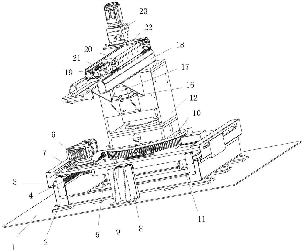
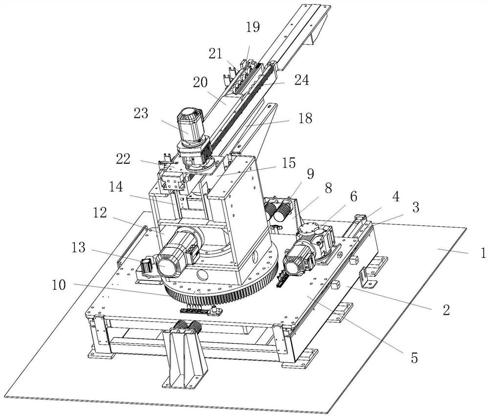
[0018] see Figure 1 to Figure 2 , the embodiment of the present invention includes:

[0019] A cutting line loading and unloading machine, comprising a displacement device fixedly installed on the bottom plate 1 and a rotary loading and unloading device, the displacement device includes a base 2 and a displacement transmission structure arranged in the base 2, the displacement transmission mechanism is fixed on A rotary loading and unloading device is provided. The rotary loading and unloading device includes a rotary jacking structure fixedly installed on the displacement transmission structure. The rotary jacking structure is fixedly installed with a ...


PUM


Abstract

The invention discloses a feeding and discharging machine for a cross cut shear line. The machine comprises a displacement device and a rotary feeding and discharging device which are fixedly installed on a bottom plate, the displacement device comprises a base and a displacement transmission structure arranged in the base, and the rotary feeding and discharging device is fixedly arranged on the displacement transmission structure. The rotary feeding and discharging device comprises a rotary jacking structure fixedly installed on the displacement transmission structure, a pallet fork structureon the rotary jacking structure is fixedly installed on the rotary jacking structure, the displacement transmission structure comprises sliding rails symmetrically arranged on the base, and racks parallel to the sliding rails are arranged on the inner wall of the base. A displacement plate is fixedly installed on the sliding block on each sliding rail, a displacement driver is arranged on each displacement plate, a displacement driving gear is fixedly arranged on an output shaft of each displacement driver, and each displacement driving gear is meshed with the corresponding rack. By means ofthe manner, automatic feeding, discharging and heavy loading can be achieved, the positioning precision is high, transportation is stable, product transfer transportation is smooth, and the transportation efficiency is greatly improved.

Description

technical field [0001] The invention relates to the field of automatic loading and unloading devices, in particular to a cross-cut line loading and unloading machine. Background technique [0002] When loading materials in the existing transformer core production workshop, the silicon steel coils are basically transported by cranes. It takes a lot of manpower to lift and lift the silicon steel coils in the three-dimensional warehouse to the cross-cutting line, and the operation of the personnel is unstable, and the product load is large, posing safety hazards. If the silicon steel coil falls during transportation, it may easily cause accidents or damage the equipment. At the same time, its accuracy and efficiency are not high, and the operation is inconvenient. Contents of the invention [0003] The technical problem mainly solved by the present invention is to provide a cross-cutting line loading and unloading machine, which can automatically load and unload materials, a...

Claims


Application Information

Patent Timeline
Patent Type & Authority Applications(China)
IPC IPC(8): B23D33/02B65G1/04
CPCB23D33/02B65G1/04
Inventor 杨兴国
Owner SUZHOU GUANKE IND EQUIP CO LTD
Why Eureka
Try Eureka