Machine tool part corner angle polishing operation device and polishing method

A technology for operating devices and parts, which is applied to the parts of grinding machine tools, grinding/polishing safety devices, and machine tools suitable for grinding the edge of workpieces, etc., which can solve the problems of wasting manpower and low work efficiency

Inactive Publication Date: 2021-03-02
安徽宇艳智能机械科技有限公司
View PDF5 Cites 4 Cited by
  • Summary
  • Abstract
  • Description
  • Claims
  • Application Information

AI Technical Summary

Problems solved by technology

[0004] In order to solve the problems raised in the above-mentioned background technology, the present invention provides an operation device and a polishing method for edge polishing of machine tool parts, which solves the problem that the edge line position of plate parts is generally polished by manual use of sandpaper, and the work efficiency cannot be improved. Low and labor-intensive issues

Method used


Image

  • Machine tool part corner angle polishing operation device and polishing method
  • Machine tool part corner angle polishing operation device and polishing method
  • Machine tool part corner angle polishing operation device and polishing method

Examples


Embodiment 1

[0045] see figure 1 , figure 2 , image 3 , Figure 4 , Figure 5 , Image 6 , Figure 7 , Figure 8 , Figure 9 , Figure 11 and Figure 14 As shown, the present invention provides the following technical solutions:

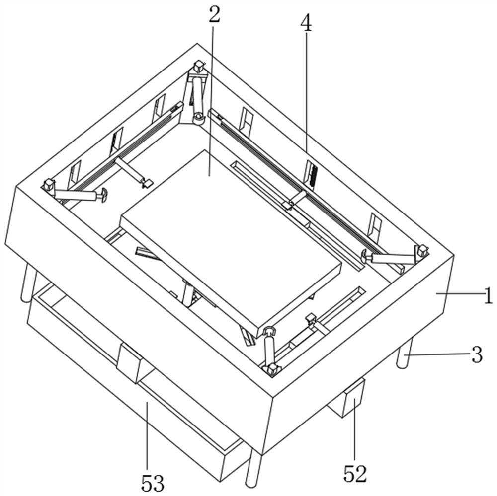
[0046] A device for polishing the edges and corners of machine tool parts, comprising a polishing base plate 1 and a machine tool part plate 2,

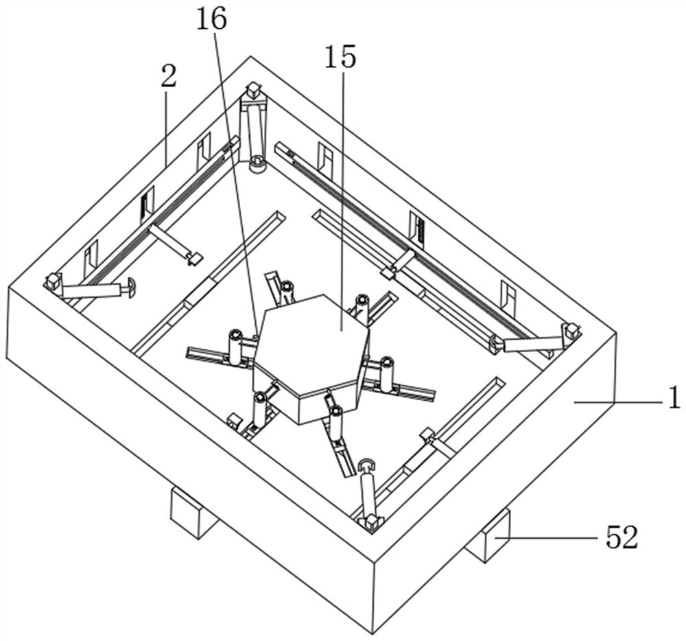
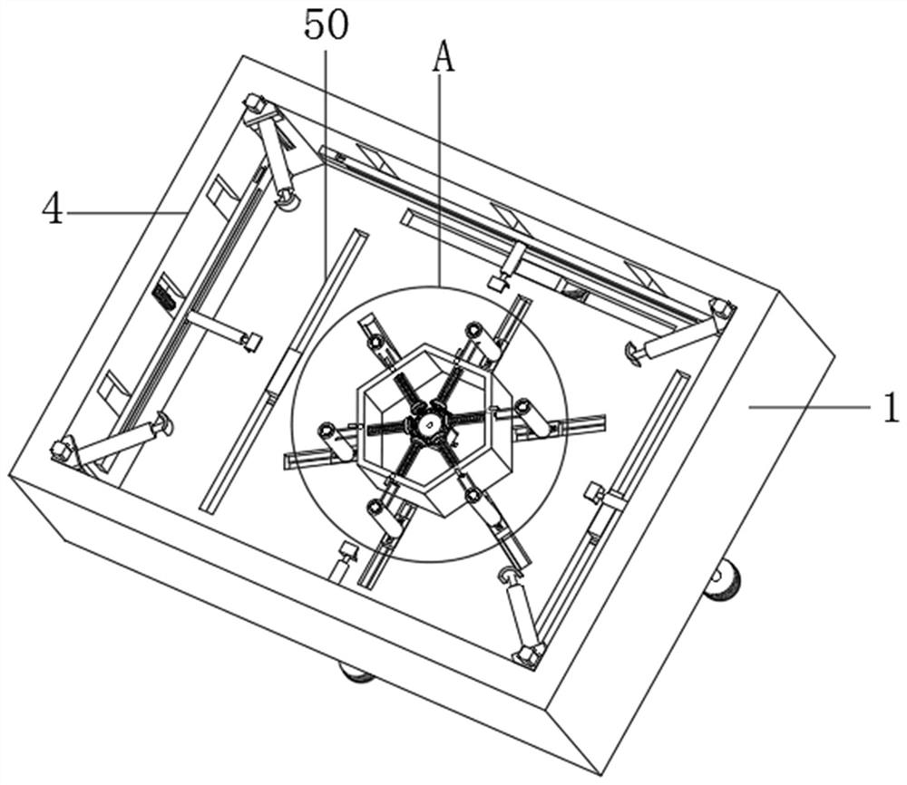
[0047] Among them, such as figure 1 and figure 2 As shown, the bottom end of the polishing substrate 1 is fixed with a support rod 3, the top center of the polishing substrate 1 is provided with a polishing rectangular groove 4, and the center of the bottom end of the polishing rectangular groove 4 is fixed with a six-sided cavity column 5, and the interior of the six-sided hollow column 5 is provided There are supporting and fixing components,

[0048] Among them, such as image 3 and Figure 4 As shown, the supporting and fixing assembly includes a servo motor 6, a central bevel gear 7, a side bevel ...

Embodiment 2

[0066] On the basis of Example 1, refer to figure 1 , Figure 4 and Figure 10 As shown, a device for polishing the edges and corners of machine tool parts:

[0067] The center of the bottom end of the polishing substrate 1 is screwed with a cross protection frame 52, the lower part of the polishing substrate 1 is provided with a receiving slot 53, and the cross protection frame 52 covers and protects the driving components. Slot 54, the bottom end of the auxiliary chute 54 is provided with a through slot 55, the through slot 55 is arranged through the bottom end of the polishing substrate 1, an auxiliary slider 56 slides inside the auxiliary chute 54, and a connecting hole 57 is opened at the top of the auxiliary slider 56 to support The bottom end of the side surface of the rod 12 is fixed with a connecting plate 58, and the connecting plate 58 and the connecting hole 57 are screwed with screws 59.

[0068] The working principle of the present invention and the use flow: ...

Embodiment 3

[0071] On the basis of Example 2, refer to Figure 11 , Figure 12 , Figure 13 , Figure 14 and Figure 15 As shown, a device for polishing the edges and corners of machine tool parts:

[0072] Two sets of first auxiliary vertical chutes 60 are symmetrically opened on the two opposite inner walls of the polishing groove 4 in the length direction with the first vertical chute 17 as a symmetrical object. Auxiliary vertical sliding block 61, two sets of second auxiliary vertical sliding grooves 62 are symmetrically opened on two opposite inner walls in the width direction of polishing rectangular groove 4 with the second vertical sliding groove 26 as a symmetrical object. A second auxiliary vertical sliding block 63 is slidably connected inside 62. The top and bottom ends of the first auxiliary vertical chute 60 are flush with the top and bottom ends of the first vertical chute 17 respectively. The second auxiliary vertical chute 62 The top and bottom ends are flush with th...


PUM


Abstract

The invention belongs to the technical field of machine tool part corner angle polishing, and particularly relates to a machine tool part corner angle polishing operation device. The machine tool partcorner angle polishing operation device comprises a polishing base plate and a machine tool part plate; supporting rods are fixed to the bottom end of the polishing base plate; a polishing rectangular groove is formed in the center of the top end of the polishing base plate; a hexahedral cavity column is fixed to the center of the bottom end of the polishing rectangular groove; a supporting fixing assembly is arranged in the hexahedral cavity column; six sets of magnetic stickers are evenly arranged on the circumference of the top end of the hexahedral cavity column; a hexahedral cover is connected to the top end of the hexahedral cavity column through the magnetic stickers; auxiliary rods are fixed to the centers of the side faces of the hexahedral cover; a horizontal polishing assemblyand a vertical polishing assembly are arranged in the polishing rectangular groove; a driving assembly is arranged at the bottom end of the polishing base plate; four sets of rectangular discharging grooves are formed in the bottom end of the rectangular polishing groove; partition plates are fixed to the middle of the rectangular discharging groove; a cross-shaped protection frame is in threadedconnection with the center of the bottom end of the polishing base plate; a collecting groove is formed in the lower portion of the polishing base plate; and the cross-shaped protection frame covers and protects the driving assembly.

Description

technical field [0001] The invention belongs to the technical field of edge and corner polishing of machine tool parts, and particularly relates to a device and a polishing method for edge and corner polishing of machine tool parts. Background technique [0002] A machine tool refers to a machine that makes a machine, also known as a work machine or a machine tool, and is customarily referred to as a machine tool. Generally divided into metal cutting machine tools, forging machine tools and woodworking machine tools. There are many ways to process mechanical parts in modern machinery manufacturing. In addition to cutting, there are casting, forging, welding, stamping, extrusion, etc., but for parts with high precision requirements and finer surface roughness requirements, generally need to be in The final machining is performed by cutting on the machine tool. Machine tools play an important role in the modernization of the national economy. [0003] The machine tool is as...

Claims


Application Information

Patent Timeline
Patent Type & Authority Applications(China)
IPC IPC(8): B24B9/04B24B29/02B24B27/00B24B41/06B24B47/16B24B47/20B24B55/06B24B55/12
CPCB24B9/04B24B27/0076B24B29/02B24B41/06B24B47/16B24B47/20B24B55/06B24B55/12
Inventor 胡学友徐庆辉杨俊宇
Owner 安徽宇艳智能机械科技有限公司
Why Eureka
Try Eureka