Hollow cable sleeve clamp and tension test equipment

A technology for tension testing and cable sheathing, which is applied in the direction of applying stable tension/pressure to test the strength of materials, measuring devices, instruments, etc., and can solve the problem of damage to hollow cable sheaths, inconvenient use by staff, and difficult side-view parameters, etc. problem, to achieve the effect of improving work efficiency

Inactive Publication Date: 2021-03-02
苏州固畅电子科技有限公司
View PDF0 Cites 3 Cited by
  • Summary
  • Abstract
  • Description
  • Claims
  • Application Information

AI Technical Summary

Problems solved by technology

[0003] However, when the existing hollow cable sheath test fixture is used, the hollow cable sheath is clamped, and the hollow cable sheath is easily clamped flat, thereby destroying the result of the tension side view and damaging the hollow cable When the existing hollow cable sleeve is tested, it is difficult to perform intuitive side-view parameters, and the staff needs to use tools to measure, which is inconvenient for the staff to use

Method used


Image

  • Hollow cable sleeve clamp and tension test equipment
  • Hollow cable sleeve clamp and tension test equipment
  • Hollow cable sleeve clamp and tension test equipment

Examples


Embodiment 1

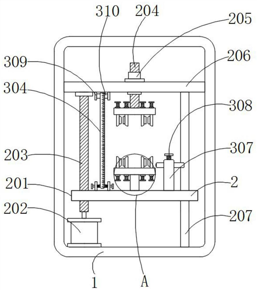
[0025] Example 1, such as Figure 1-4 As shown, the present invention provides a hollow cable sheath fixture and tensile testing equipment, including a box body 1 , a clamping mechanism 2 is arranged inside the box body 1 , and a measuring mechanism 3 is arranged inside the clamping mechanism 2 .

[0026] Let's talk about the specific settings and functions of the clamping mechanism 2 and the measuring mechanism 3 in detail.

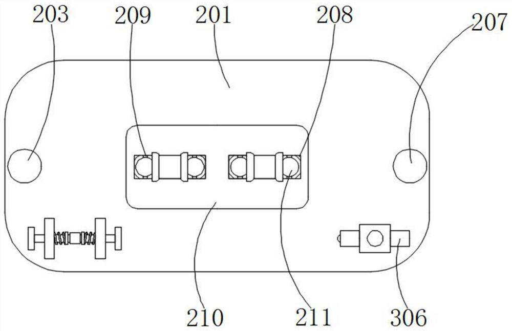
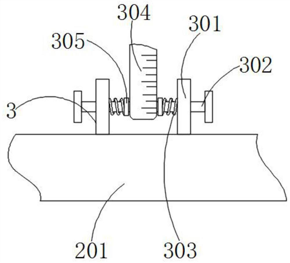
[0027] Such as figure 1 , figure 2 with Figure 4 As shown, the clamping mechanism 2 includes a DC motor 202, the output shaft at the top of the DC motor 202 is fixedly connected with a first threaded rod 203, and the outer surface of the first threaded rod 203 is threaded with an operation panel 201, and the operation panel 201 is close to the left side The inner slide of the first threaded rod 203 is embedded with a limit rod 207, the top of the first threaded rod 203 is fixedly connected with a fixed plate 206 through a bearing, and the center of ...


PUM


Abstract

The invention provides a hollow cable sleeve clamp and tension testing equipment, and relates to the technical field of tension testing. The hollow cable sleeve clamp comprises a box body, a clampingmechanism is arranged in the box body, a measuring mechanism is arranged in the clamping mechanism, the clamping mechanism comprises a direct current motor, and an output shaft at the top of the direct current motor is fixedly connected with a first threaded rod; and the outer surface of the first threaded rod is provided with an operation plate in a threaded mode. According to the invention, twothird threaded rods are adjusted through two rectangular through holes so that four third threaded rods at the top and four buffer plates clamp the inner walls of the two sides of a hollow cable sleeve, then four second limiting sleeves are rotated, the hollow cable sleeve is clamped through the four buffer plates, and at the moment, the other end of the hollow cable sleeve is clamped; and the hollow cable sleeve is clamped through the four buffer plates and the four second limiting sleeves so that the hollow cable sleeve is fixed, a tension test is carried out on the hollow cable sleeve, anddeformation of the hollow cable sleeve during clamping is prevented.

Description

technical field [0001] The invention relates to the technical field of tensile testing, in particular to a hollow cable sheath fixture and tensile testing equipment. Background technique [0002] The tensile test should be supplemented by a burst test. This tensile test plays a role in guaranteeing the sealing quality and is a mandatory test method. It can be divided into static tensile test and dynamic tensile test. With the development of society, tensile test has been widely used, and the hollow cable sleeve also needs to be viewed from the side of the tensile force to facilitate the quality of the hollow cable sleeve; [0003] However, when the existing hollow cable sheath test fixture is used, the hollow cable sheath is clamped, and the hollow cable sheath is easily clamped flat, thereby destroying the result of the tension side view and damaging the hollow cable When the existing hollow cable sleeve is tested, it is difficult to perform intuitive side-view parameters...

Claims


Application Information

Patent Timeline
Patent Type & Authority Applications(China)
IPC IPC(8): G01N3/04G01N3/08
CPCG01N3/04G01N3/08
Inventor 府国新
Owner 苏州固畅电子科技有限公司
Why Eureka
Try Eureka