A laser attenuator with large magnification and continuously adjustable magnification

A technology of laser attenuation and large magnification, which is applied in the direction of lasers, laser components, phonon exciters, etc., can solve the problems that the attenuation magnification cannot be satisfied, the attenuation magnification cannot be continuously adjusted, and the attenuation magnification cannot be continuously adjusted. Achieve the effect of simple structure, low cost and large attenuation magnification

Active Publication Date: 2022-05-10
XI'AN INST OF OPTICS & FINE MECHANICS - CHINESE ACAD OF SCI
View PDF11 Cites 0 Cited by
  • Summary
  • Abstract
  • Description
  • Claims
  • Application Information

AI Technical Summary

Problems solved by technology

[0003] The Chinese patent document with the application number 200720031746.4 discloses a laser attenuator, which uses two split plate pairs to form an optical hinge, and coats the opposite working surfaces of the two split plates in sections to achieve different light intensities during the overall movement of the optical hinge. The attenuation of the magnification, but this scheme cannot realize the continuous adjustment of the attenuation magnification, and the attenuation magnification still cannot meet the requirements of the current high power / energy laser measurement system
[0004] The Chinese patent document with the application number 201510941066.5 discloses a coded high-magnification laser attenuator. The different gears of the attenuation plate can be switched, and the attenuation magnification code is adjustable, which can achieve a larger magnification attenuation, but still cannot achieve the attenuation magnification. Continuously adjustable, and the attenuation ratio still cannot meet the requirements of current high power / energy laser measurement systems

Method used


Image

  • A laser attenuator with large magnification and continuously adjustable magnification
  • A laser attenuator with large magnification and continuously adjustable magnification
  • A laser attenuator with large magnification and continuously adjustable magnification

Examples


Embodiment 1

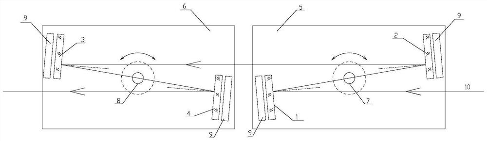
[0030] like figure 1 As shown, the laser attenuator with large magnification and continuously adjustable magnification provided by this embodiment includes Fresnel reflector 1, Fresnel reflector 2 2, Fresnel reflector 3 3, Fresnel reflector Four 4, base plate one 5, base plate two 6, rotating shaft one 7, rotating shaft two 8 and absorber 9.

[0031] Fresnel reflector 1, Fresnel reflector 2 2 are installed on the base plate 1 5, base plate 1 5 can rotate around the rotating shaft 7; Fresnel reflector 3 3, Fresnel reflector 4 4 are installed on the base plate On the second 6, the base plate two 6 can rotate around the rotating shaft two 8; an absorber 9 is arranged behind each Fresnel reflector, and the absorber 9 is used to absorb the light passing through the Fresnel reflector, so as to avoid Stray light is generated in the middle, and the absorber 9 is a neutral glass selected according to the laser wavelength.

[0032] Fresnel reflector 1, Fresnel reflector 2 2, Fresnel r...

Embodiment 2

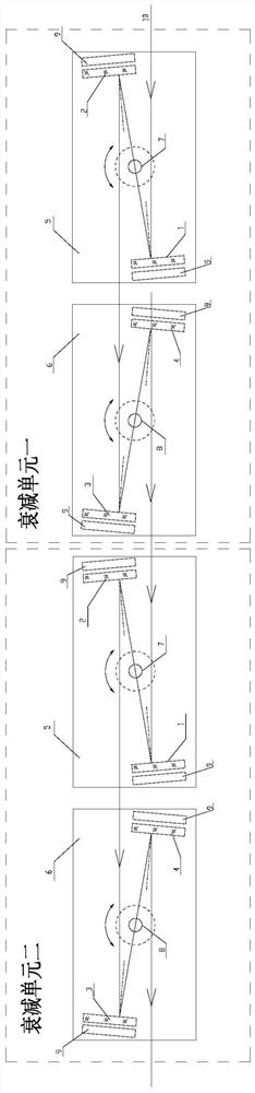
[0045]The difference between this embodiment and Embodiment 1 is that in this embodiment, the laser attenuator shown in Embodiment 1 is cascaded in two stages (that is, the input laser of attenuation unit 2 is the output laser of attenuation unit 1), so as to achieve more In the laser attenuator with large attenuation ratio and adjustable ratio, the laser attenuation unit 1 and the laser attenuation unit 2 work independently, and the working principle is the same as that of the first embodiment, which will not be repeated here.

[0046] In other embodiments, Embodiment 1 may also be an attenuation unit, and more stages of cascading may be performed (the number of attenuation units is an even number).

Embodiment 3

[0048] The difference between this embodiment and the first embodiment is that the four Fresnel reflectors in the first embodiment are replaced by coated reflectors with a wedge-shaped structure and coated with a partial reflective film.


PUM

PropertyMeasurementUnit
reflectanceaaaaaaaaaa

Abstract

In order to meet the technical requirements of the high power / energy laser measurement system that the attenuator's attenuation magnification is large enough, the attenuation is stable, and can be adjusted continuously to a certain extent, and the optical axis of the measurement system will not be shifted during the adjustment process, the present invention proposes a Large magnification and magnification continuously adjustable laser attenuator, including one attenuation unit or multiple attenuation units in series; a single attenuation unit includes four identical wedge-shaped Fresnel reflectors and two base plates; one Fresnel reflector 1. The second interval is set on the base plate 1, and the reflection surfaces of the two are opposite and parallel; the third and fourth Fresnel reflectors are arranged on the base plate 2, and the two reflection surfaces are opposite and parallel; the base plates 1 and 2 can rotate around their respective rotation axes; The incidence angles of the laser light incident on the Fresnel reflectors 1 to 4 are all equal; after being installed in place, the optical elements on the base plate 1 and the base plate 2 and the optical elements on the base plate form a mirror image relationship.

Description

technical field [0001] The invention belongs to the field of high power / energy laser measurement technology and equipment, and relates to a laser attenuator with large magnification and continuously adjustable magnification. Background technique [0002] In a high-power / energy laser measurement system, the laser energy injected into the measurement system is often on the order of tens of thousands of joules (j), while the energy that the detector (such as a CCD) can respond to is between microjoules (μj) and nanojoules (nj). Therefore, the attenuation of large magnification is a must configuration for measurement. The requirement for attenuation is that the magnification is large enough, the attenuation is stable, and to a certain extent, the attenuation must be continuously adjustable to adapt to the best response range of the detector; at the same time, In the high power / energy measurement system, the optical path must be aligned in the weak light state before the laser is...

Claims


Application Information

Patent Timeline
Patent Type & Authority Patents(China)
IPC IPC(8): H01S3/10
CPCH01S3/10023
Inventor 达争尚李红光高立民董晓娜孙策
Owner XI'AN INST OF OPTICS & FINE MECHANICS - CHINESE ACAD OF SCI
Why Eureka
Try Eureka