Rotor, motor, compressor and refrigeration equipment
A rotor and rotor core technology, applied in the field of compressors, can solve problems affecting the competitiveness of compressor products, motor noise, etc., achieve good noise reduction effects, improve noise, and optimize the effect of air gap flux density waveforms
- Summary
- Abstract
- Description
- Claims
- Application Information
AI Technical Summary
Problems solved by technology
Method used
Image

Examples
Embodiment 1
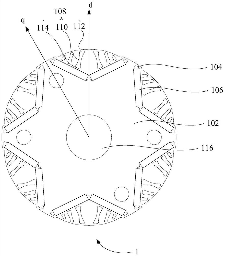
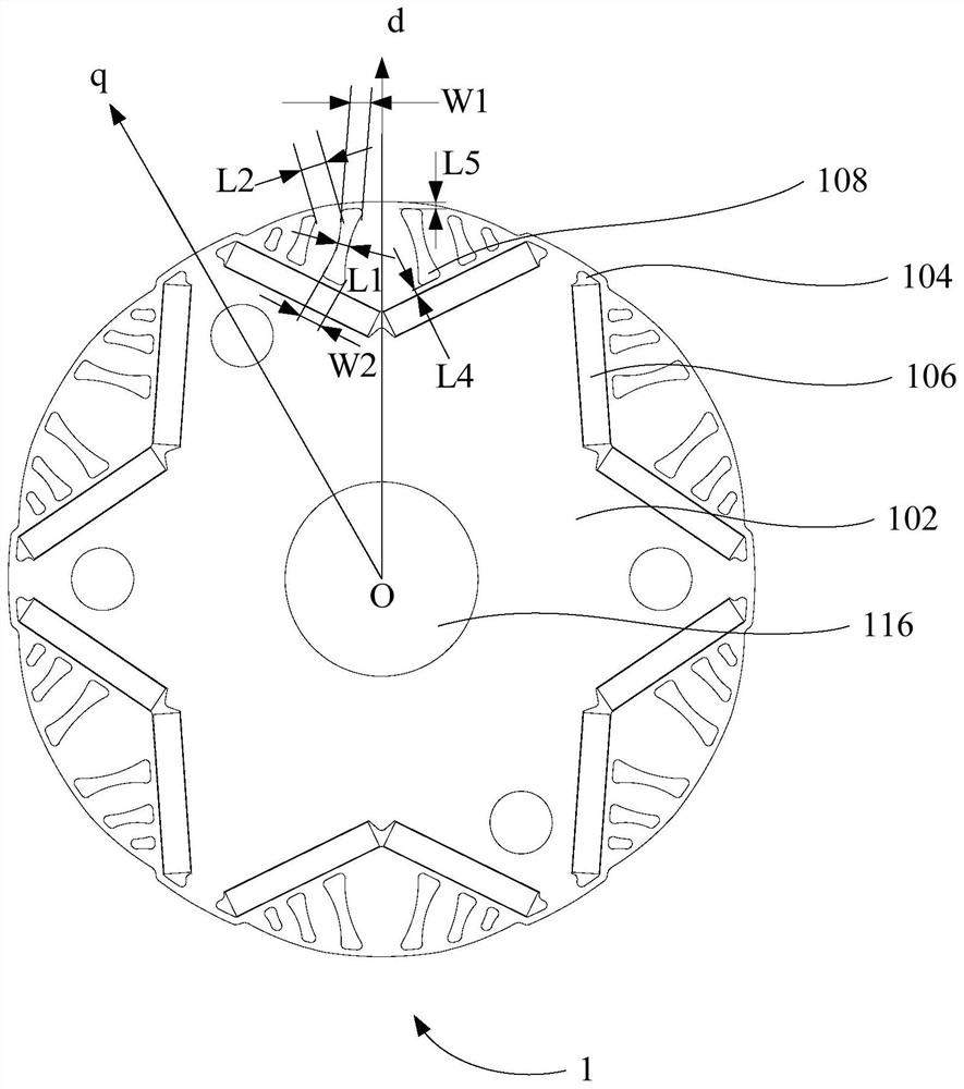
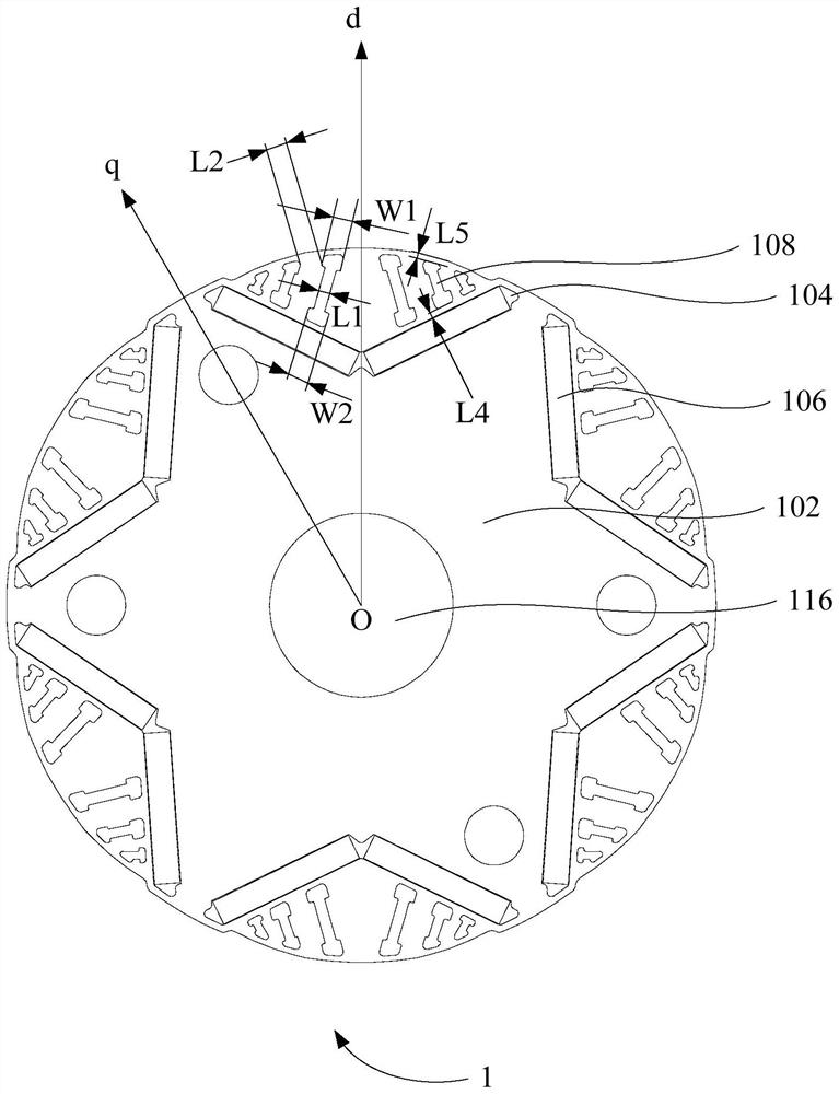
[0060] Such as Figure 1 to Figure 4 As shown, according to the first aspect of the present invention, a rotor 1 is provided, including: a rotor core 102, a permanent magnet 106 and a plurality of slits, the plurality of slits include at least one first slit 108, a plurality of The slits are arranged on the rotor core 102 on the side of the mounting groove 104 away from the axis of the rotor core 102, and the minimum distance between two adjacent slits among the plurality of slits is L2; wherein, the first slit 108 The minimum value L1 of the width of the first slit 108 is set between two ends along the length direction, and L2 is greater than or equal to 0.5 times L1.
[0061] Specifically, the rotor core 102 is provided with an installation groove 104, and the permanent magnet 106 is arranged in the installation groove 104 and forms a magnetic pole, and is arranged on the rotor core 102 on the side of the installation groove 104 away from the axis of the rotor core 102 thr...
Embodiment 2
[0067] Such as Figure 1 to Figure 4As shown, in one embodiment of the present invention, the rotor 1 includes: a rotor core 102, a permanent magnet 106, a first slit 108 and a second slit (not shown), wherein, based on the distance between the d-axis and the q-axis The rotor core 102 is provided with a plurality of slits, the plurality of slits include: at least two first slits 108; or at least one first slit 108 and at least one second slit, the second slit is located at The rotor core 102 between the adjacent d-axis and q-axis is located on one side or both sides of at least one first slit 108 .
[0068] In this embodiment, it is defined that the number of slits on the rotor core 102 between adjacent d-axes and q-axes is multiple. On the one hand, the multiple slits include at least two first slits 108, namely The multiple slits on the rotor core 102 between the d-axis and the q-axis are all first slits 108; on the other hand, the multiple slits include at least one first ...
Embodiment 3
[0075] Such as Figure 1 to Figure 4 As shown, in one embodiment of the present invention, the rotor 1 includes: a rotor core 102, a permanent magnet 106, a first slit 108, a second slit, and a transition portion 110 of the first slit 108, wherein the transition portion 110 The minimum value of the width is L1, and in a plane perpendicular to the axis of the rotor core 102, the side of the transition portion 110 is at least one of the following: a straight line, a curved line, or a bent line.
[0076] In this embodiment, the first slit 108 includes a transition portion 110 , and the minimum width of the transition portion 110 is L1, that is, the minimum width of the first slit 108 is located at the transition portion 110 , perpendicular to the rotor core 102 In the plane of the axis, the side of the transition part 110 is a straight line, a curve, a bent line or a combination thereof, and the transition part 110 can be reasonably set according to different positions, different...
PUM
 Abstract
Description
Claims
Application Information
 - R&D
- Intellectual Property
- Life Sciences
- Materials
- Tech Scout
- Unparalleled Data Quality
- Higher Quality Content
- 60% Fewer Hallucinations
Browse by: Latest US Patents, China's latest patents, Technical Efficacy Thesaurus, Application Domain, Technology Topic, Popular Technical Reports.
© 2025 PatSnap. All rights reserved.Legal|Privacy policy|Modern Slavery Act Transparency Statement|Sitemap|About US| Contact US: help@patsnap.com