Control valve

A technology for controlling valves and valve seats, applied to valve details, valve devices, valve housing structures, etc., can solve problems such as high energy consumption, heating methods that cannot be applied to new energy vehicles, and impact on the mileage of new energy vehicles

Pending Publication Date: 2021-03-05
ZHEJIANG SANHUA AUTOMOTIVE COMPONENTS CO LTD
View PDF0 Cites 1 Cited by
  • Summary
  • Abstract
  • Description
  • Claims
  • Application Information

AI Technical Summary

Problems solved by technology

[0002] With the development of new energy vehicles, the requirements for automotive air conditioning systems are getting higher and higher, but the heating method of traditional vehicles cannot be applied to new energy vehicles, and the electric heating method consumes a lot of energy and affects the driving of new energy vehicles mileage

Method used


Image

  • Control valve
  • Control valve
  • Control valve

Examples


Embodiment Construction

[0021] DETAILED DESCRIPTION OF THE INVENTION The specific embodiments of the present invention will be described below with reference to the drawings.

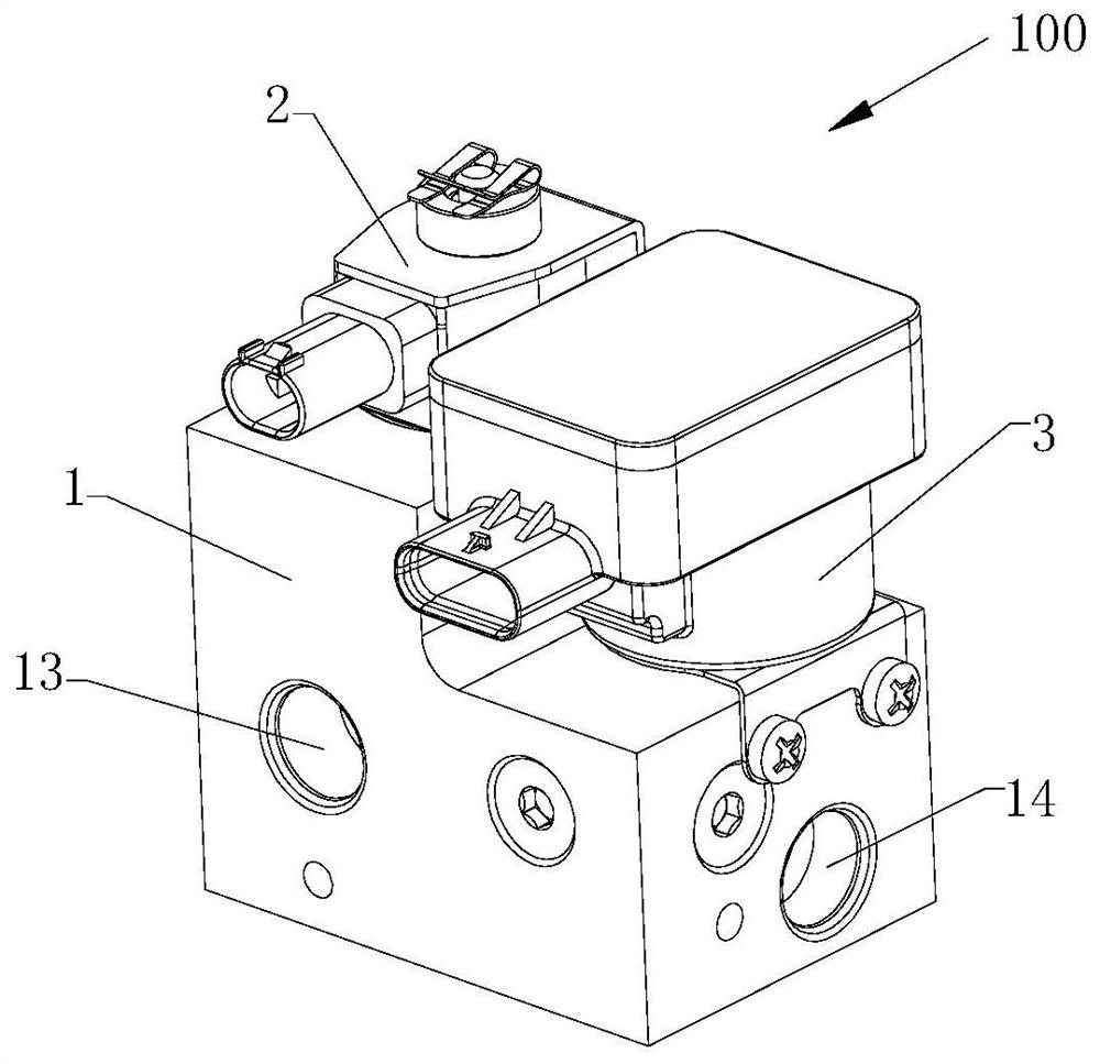
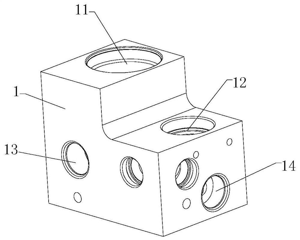
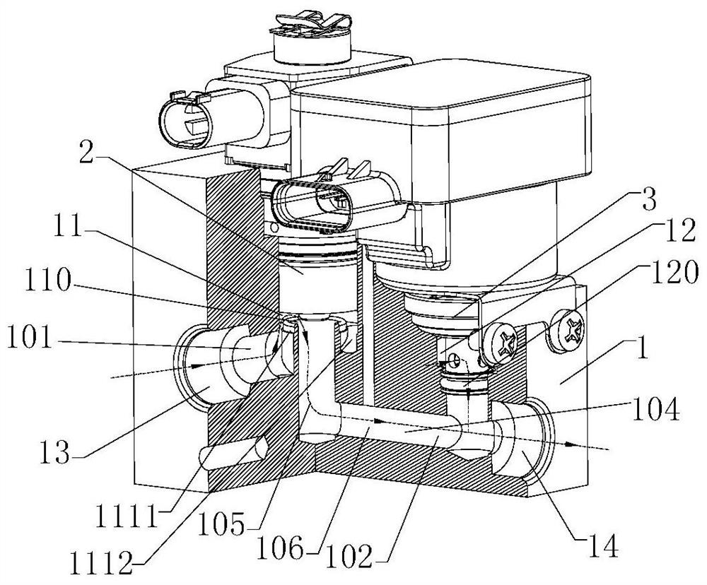
[0022] Please refer to Figure 1 to 6 As shown, a control valve 100 includes a valve seat 1 and a solenoid spool member 2, a valve seat 1 including a first valve chamber 11, and the solenoid spool member 2 is at least partially located at the first valve chamber 11, the solenoid spool member 2. The portion is fixed to the valve seat 1, and the solenoid spool member is fixed by a threaded connection. The valve seat 1 also includes a first interface passage 101 and a second interface passage 102, and the first interface passage 101 communicates with the first valve chamber 11, and the control valve 100 can control the first interface passage 101 and the second interface passage 102.

[0023] The control valve 100 also includes a throttle core member 3, and the valve seat 1 further includes a second valve chamber 12, and the throttle ...


PUM


Abstract

The invention provides a control valve. The control valve comprises a valve seat and an electromagnetic valve element component. The valve seat comprises a first valve cavity. At least part of the electromagnetic valve element component is located in the first valve cavity. The electromagnetic valve element component and the valve seat are fixedly arranged. The valve seat further comprises a firstconnector channel and a second connector channel. The first connector channel communicates with the first valve cavity. The electromagnetic valve element component can control the first connector channel and the second connector channel to be connected and disconnected. The control valve further comprises a throttling valve element component. The valve seat further comprises a second valve cavity. At least part of the throttling valve element component is located in the second valve cavity. The throttling valve element component and the valve seat are fixedly arranged. The valve seat furthercomprises a first runner. The first runner is connected with the first connector channel and the second valve cavity. The second valve cavity communicates with the second connector channel. The throttling valve element component can control the first runner and the second connector channel to be connected and disconnected and control the fluid flow. The throttling valve element component is integrated on the valve seat of the control valve, and connecting pipelines between the control valve and a throttling valve can be relatively reduced.

Description

Technical field [0001] The present invention relates to the field of fluid control technology, and more particularly to a control valve. Background technique [0002] With the development of new energy vehicles, the requirements for automotive air conditioning systems are getting higher and higher, but the heating method of traditional cars cannot be applied to new energy vehicles, while electric heating is high, affecting new energy vehicles. mileage. The heat pump system has begun to be applied to new energy vehicle air conditioners. Since the heat pump system is complicated to the traditional refrigeration system, there are many parts, how to improve the number of components of the system to reduce the pipeline between components is research direction. one. Inventive content [0003] The technical solution provides a new structure of the control valve, which uses the following technical solution: a control valve including a valve seat and a solenoid spool member including a f...

Claims


Application Information

Patent Timeline
Patent Type & Authority Applications(China)
IPC IPC(8): F16K47/04F16K31/06F16K27/00
CPCF16K27/00F16K31/0644F16K47/04
Inventor 不公告发明人
Owner ZHEJIANG SANHUA AUTOMOTIVE COMPONENTS CO LTD
Why Eureka
Try Eureka