Light source system and lighting device

A light source system and a technology for exciting a light source, applied in the optical field, can solve the problems of complex optical path design, increase the volume and cost of the light source, reduce the light collection efficiency of the light source, etc., and achieve the effect of improving color uniformity and improving the halo problem.

Active Publication Date: 2021-03-05
SHENZHEN LASER INST
View PDF20 Cites 0 Cited by
  • Summary
  • Abstract
  • Description
  • Claims
  • Application Information

AI Technical Summary

Problems solved by technology

However, the introduction of components such as fly-eye lenses or square rods complicates the optical path design, which not

Method used


Image

  • Light source system and lighting device
  • Light source system and lighting device
  • Light source system and lighting device

Examples


Embodiment 1

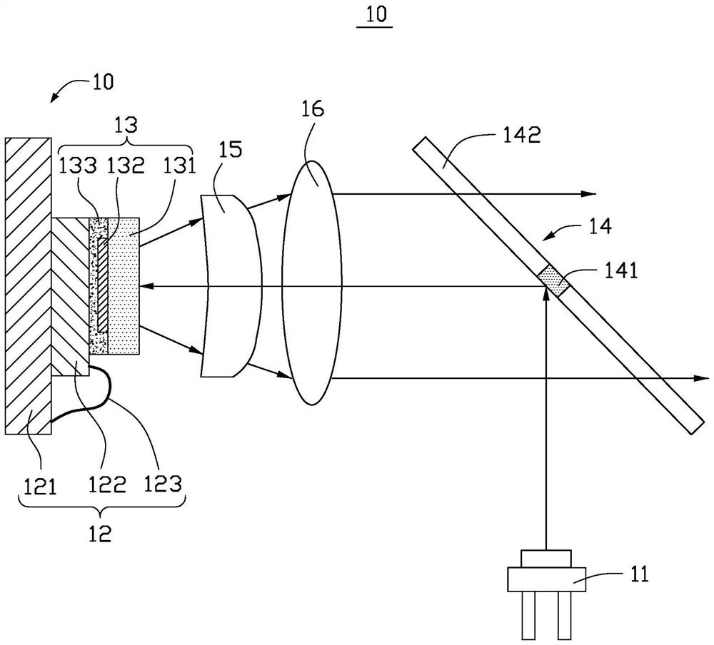
[0019] see figure 1 The light source system 10 provided in this embodiment includes a first excitation light source 11 , a second excitation light source 12 and a wavelength conversion structure 13 , and the first excitation light source 11 and the second excitation light source 12 are respectively located on both sides of the wavelength conversion structure 13 .

[0020] The first excitation light source 11 is used to emit a first excitation light. In this embodiment, the first excitation light source 11 is a laser or a laser array, that is, the first excitation light is a laser.

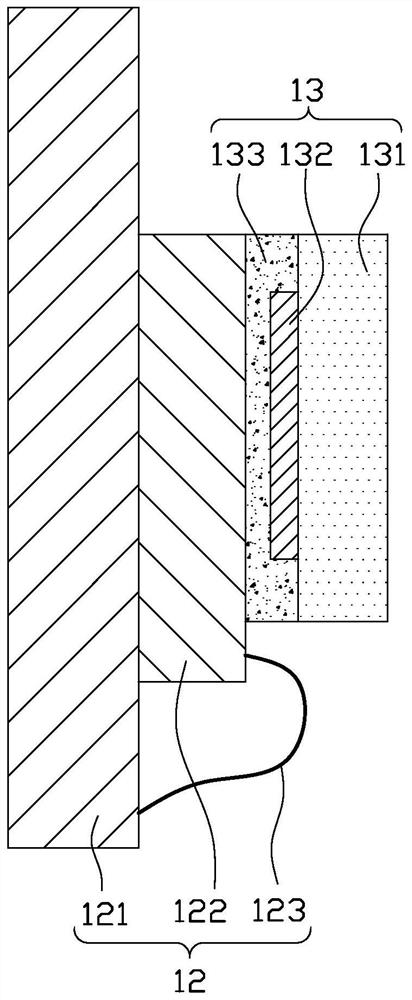
[0021] see figure 2 , the second excitation light source 12 includes a substrate 121 , a light emitting device 122 disposed between the substrate 121 and the wavelength conversion structure 13 , and wires 123 for electrically connecting the substrate 121 and the light emitting device 122 respectively.

[0022] Wherein, the substrate 121 is used to carry the light emitting device 122 . In this em...


PUM


Abstract

The invention provides a light source system. The light source system comprises: a first exciting light source, used for emitting first exciting light; a wavelength conversion structure, comprising awavelength conversion material layer used for receiving the first exciting light and converting at least part of the first exciting light into first excited light to be emitted out, wherein a transmission area and a non-transmission area surrounded by the transmission area are defined on the face, opposite to the incident face of the first exciting light, of the wavelength conversion material layer; and a second exciting light source, arranged on the side, away from the incident face of the first exciting light, of the wavelength conversion structure and used for emitting second exciting light, wherein the second exciting light enters the wavelength conversion material layer from the transmission area, and the wavelength conversion material layer converts at least part of the second exciting light into second excited light to be emitted out and transmits the part, not absorbed by the wavelength conversion material layer, of the second exciting light. The invention further provides a lighting device.

Description

technical field [0001] The invention relates to the field of optical technology, in particular to a light source system and an illuminating device using the light source system. Background technique [0002] In the lighting field of laser remote excitation phosphor technology, blue laser is usually used to excite yellow fluorescent material layer to produce yellow fluorescence, and yellow fluorescence is combined with blue laser to produce white light. When the laser beam is gathered into a spot and illuminates the surface of the fluorescent material layer, there is a "spot spreading phenomenon", that is, the phenomenon that the area A' of the light-emitting spot after excitation is larger than the actual area A of the excitation spot. In the field of lighting applications, this diffusion phenomenon will cause a "yellow circle" problem on the edge of the finally projected white light beam spot, which seriously affects the color uniformity of the spot. [0003] At present, a...

Claims


Application Information

Patent Timeline
IPC IPC(8): F21V9/32F21Y115/10
CPCF21V9/32F21Y2115/10F21Y2115/30F21K9/64F21Y2113/20H01S5/0087
Inventor 李乾陈雨叁王艳刚
Owner SHENZHEN LASER INST
Why Eureka
Try Eureka