
Air conditioner

A technology for air conditioners and defrosting heat exchangers, which is applied in air conditioning systems, space heating and ventilation, and compression machines with reversible cycles, etc. It can solve the problems of long defrosting time, increased gas flow resistance, and blockage of the evaporator surface To achieve the effect of improving thermal comfort, maximizing capacity, and fast defrosting speed

Inactive Publication Date: 2021-03-05
QINGDAO HISENSE HITACHI AIR CONDITIONING SYST
View PDF6 Cites 2 Cited by
  • Summary
  • Abstract
  • Description
  • Claims
  • Application Information

AI Technical Summary

Problems solved by technology

[0003] There is a big problem in the heating operation of the air source heat pump: when the outdoor temperature and humidity reach certain conditions, frost will form on the air side of the outdoor heat exchanger, and as the amount of frost increases, the surface of the evaporator will gradually be blocked , leading to a decrease in the surface heat transfer coefficient of the outdoor heat exchanger and an increase in the gas flow resistance, which seriously affects the heating effect of the machine. Therefore, the unit needs to be defrosted regularly
[0006] This defrosting method has the following disadvantages: 1. Use the heat converted by part of the power consumption of the compressor to defrost, which belongs to low-pressure defrosting, with less heat and long defrosting time; 2. When hot gas bypass defrosting, use low-pressure sensible heat to defrost , the temperature is low, the heat exchange temperature difference with the frost layer is small, and the defrosting reliability is poor; 3. Although the refrigerant flow direction is not changed during defrosting, the refrigerant flow of the indoor unit is very small, and the system does not supply heat to the indoor unit. Reduced indoor temperature and poor user comfort

Method used


Image

  • Air conditioner
  • Air conditioner

Examples


Embodiment Construction

[0060] The following will clearly and completely describe the technical solutions in the embodiments of the present invention with reference to the accompanying drawings in the embodiments of the present invention. Obviously, the described embodiments are only some, not all, embodiments of the present invention.

[0061] Based on the embodiments of the present invention, all other embodiments obtained by persons of ordinary skill in the art without making creative efforts belong to the protection scope of the present invention. In describing the present invention, it is to be understood that the terms "center", "upper", "lower", "front", "rear", "left", "right", "vertical", "horizontal", The orientations or positional relationships indicated by "top", "bottom", "inner", "outer", etc. are based on the orientations or positional relationships shown in the drawings, and are only for the convenience of describing the present invention and simplifying the description, rather than in...


PUM


Abstract

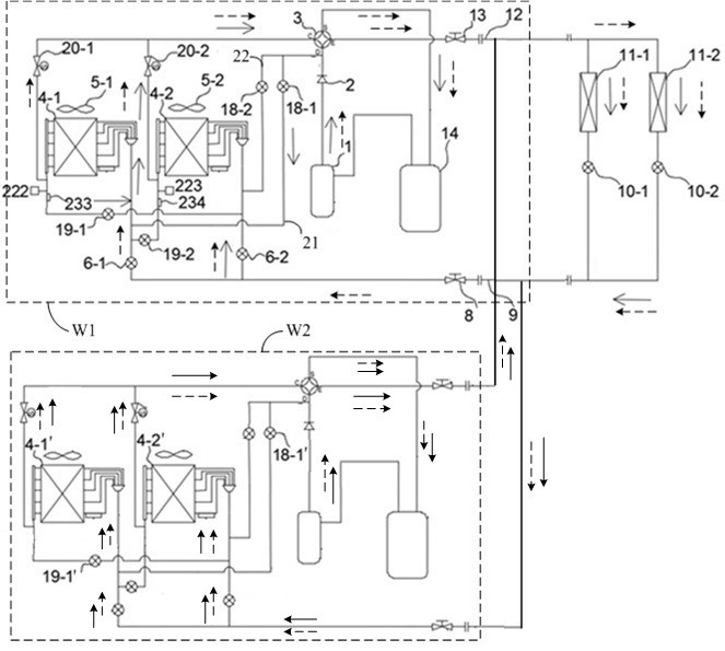
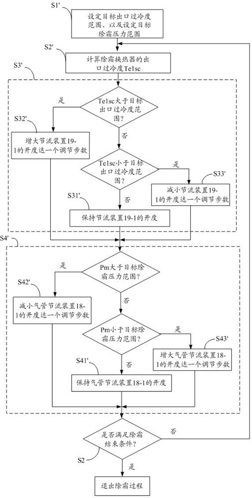
The invention discloses an air conditioner. The air conditioner comprises at least one indoor unit, a plurality of outdoor unit modules, wherein each outdoor unit module comprises a compressor; a flowpath switching device; two outdoor heat exchangers; two liquid pipe throttling devices; and two air side valves; a defrosting loop, wherein the defrosting loop is used for branching a part of a refrigerant discharged by the compressor and correspondingly selecting one of the outdoor heat exchangers to enable the refrigerant to flow in; and two throttling devices, wherein one end of each throttling device is connected with a main air pipe of the corresponding outdoor heat exchanger, and the other end of each throttling device is connected with the liquid pipe throttling device of the other corresponding outdoor heat exchanger and connected to the position of a main liquid pipe of the other outdoor heat exchanger, and a control device controls the outdoor heat exchangers to be defrosted tobe subject to sequential alternate defrosting or controls a combination of outdoor heat exchangers to be defrosted from each of the outdoor unit modules to be subject to combined alternate defrosting.According to the air conditioner, pressure-controlled defrosting can be performed on the defrosting heat exchangers while continuous heating of an air conditioning system and maximization of the indoor unit capacity are kept, and the defrosting efficiency and the indoor thermal comfort are improved.

Description

technical field [0001] The invention relates to the technical field of air conditioners, in particular to air conditioners. Background technique [0002] The technology of multi-connected air source heat pumps is becoming more and more mature, and it is widely used in household and commercial fields. The multi-connected air source heat pump includes at least one indoor unit and at least one outdoor unit module. When there are two or more indoor units, the indoor units are arranged side by side and each indoor unit has an indoor heat exchanger and a corresponding indoor fan. When there are two or more outdoor unit modules, each outdoor unit module is arranged side by side and each outdoor unit module has a frequency conversion compressor, a four-way valve, a throttling element, at least one outdoor heat exchanger and an outdoor For the fan, when there are at least two outdoor heat exchangers in one outdoor unit module, the outdoor heat exchangers are arranged side by side. ...

Claims


Application Information

Patent Timeline
Patent Type & Authority Applications(China)
IPC IPC(8): F25B13/00F25B41/20F25B47/02F25B49/02F24F5/00
CPCF24F5/001F25B13/00F25B47/025F25B2313/0251F25B2313/02741F25B2313/029F25B2400/19
Inventor 张恒董辰孟建军夏兴祥
Owner QINGDAO HISENSE HITACHI AIR CONDITIONING SYST
Learn More