Supercharge Your Innovation With Domain-Expert AI Agents!

Calibration method of shape measuring device, reference device and detector

A technology for measuring devices and detectors, which is applied to measuring devices, grinding devices, optical devices, etc., and can solve problems such as the decline in measurement accuracy of the upper surface of workpieces

Active Publication Date: 2022-06-24
SUMITOMO HEAVY IND LTD
View PDF9 Cites 0 Cited by
  • Summary
  • Abstract
  • Description
  • Claims
  • Application Information

AI Technical Summary

Problems solved by technology

If high-precision zero point calibration is not performed, the measurement accuracy of the straightness of the upper surface of the workpiece will decrease

Method used


Image

  • Calibration method of shape measuring device, reference device and detector
  • Calibration method of shape measuring device, reference device and detector
  • Calibration method of shape measuring device, reference device and detector

Examples


Embodiment Construction

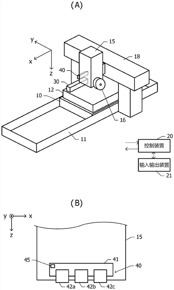
[0046] Below, refer to Figure 1 to Figure 11 , the shape measuring apparatus of the embodiment will be described.

[0047] figure 1Center (A) is a perspective view of a grinding device in which the shape measuring device of the present embodiment is incorporated. The grinding device includes: a movable table 10 , a table guide mechanism 11 , a grinding wheel head 15 , a grinding wheel 16 , a guide rail 18 , a control device 20 , an input and output device 21 , a reference device 30 and a detector 40 . The movable table 10 can reciprocate in one direction in the horizontal plane by the drive of the table guide mechanism 11 . The object to be ground (ie, the workpiece 12 ) is supported on the movable table 10 . The workpiece 12 corresponds to a measurement object whose straightness is measured by a shape measuring device.

[0048] The grinding wheel head 15 is supported by the guide rail 18 above the workpiece 12 on the movable table 10 so as to be able to move up and down....


PUM


Abstract

The invention provides a shape measuring device, which is not easy to produce deviation of the zero point position in the zero point calibration of the detector. The detector includes at least three displacement gauges arranged in a row, and is arranged to face the object to be measured so as to detect the displacement of the distance from the at least three displacement gauges to the object to be measured. The reference is supported on the support member to provide a reference surface for calibration of the detector. The control device performs the calibration of the detector. The reference device has two supporting structures supported on the supporting member in the direction in which at least three displacement gauges are arranged. The control device calibrates the detector under the condition that the reference plane is placed on at least three displacement gauges.

Description

[0001] This application claims priority based on Japanese Patent Application No. 2019-158610 filed on August 30, 2019. The entire contents of the Japanese application are incorporated herein by reference. technical field [0002] The present invention relates to a shape measuring device, a method for calibrating a detector mounted on the shape measuring device, and a reference device used for calibrating the detector. Background technique [0003] As a method of measuring the straightness of the upper surface of an object to be ground (that is, a workpiece), there is known an on-machine measurement method that scans the machined surface by attaching a displacement gauge to a grinding wheel head using the workpiece feed function of a grinding device. . In the machine measurement method, the successive three-point method using a detector including three displacement meters is generally used (for example, Patent Document 1). In the successive three-point method, the positions...

Claims


Application Information

Patent Timeline
Patent Type & Authority Patents(China)
IPC IPC(8): G01B21/20G01B21/24G01B21/04
CPCG01B21/20G01B21/24G01B21/042G01B11/245G01B11/306G01B9/02049G01B9/02061G01B11/026B24B37/04
Inventor 高娜市原浩一
Owner SUMITOMO HEAVY IND LTD
Features
  • R&D
  • Intellectual Property
  • Life Sciences
  • Materials
  • Tech Scout
  • Unparalleled Data Quality
  • Higher Quality Content
  • 60% Fewer Hallucinations
Learn More