
Backlight module, display equipment and control method of display equipment

A technology for backlight modules and display equipment, which is applied in optics, nonlinear optics, instruments, etc., and can solve problems such as halo on the display screen.

Pending Publication Date: 2021-03-05
HUIZHOU VISION NEW TECH CO LTD
View PDF3 Cites 2 Cited by
  • Summary
  • Abstract
  • Description
  • Claims
  • Application Information

AI Technical Summary

Problems solved by technology

[0005] The technical problem to be solved by the present invention is to provide a backlight module, a display device and its control method for the above-mentioned defects of the prior art, aiming at solving the problem of halos appearing on the periphery of the image display area of ​​the existing display screen

Method used


Image

  • Backlight module, display equipment and control method of display equipment
  • Backlight module, display equipment and control method of display equipment
  • Backlight module, display equipment and control method of display equipment

Examples


Embodiment 1

[0056] Such as Figure 9 As shown, the upper electrode 42 is a full surface electrode, the first electrode 421 is connected to the IC bus 422; the lower substrate 45 is provided with several TFT8 on the side of the polymer dispersion liquid crystal layer 43, several The source line 6 and a plurality of gate lines 7, the plurality of TFT8 corresponding to the plurality of lower electrodes 44 and electrically connected, the number of the gate line 7 and the array of the lower electrode 44 The number of lines is equal, and each row of mid-down electrode 44 is electrically connected to the gate line 7; the number of source lines 6 is equal to the number of arrays of the lower electrode 44, and each column Both the lower electrode 44 is electrically connected to the source line 6 by the corresponding TFT8; the signal source includes a gate driving IC71 and a source driving IC 61, and the plurality of gate lines 7 are connected in parallel to the gate drive IC71, the plurality of source...

Embodiment 2

[0058] Such as Figure 10 As shown, the upper electrode 42 is connected to the IC bus 422; the lower electrode 45 is provided with several wires 442 towards the polymer dispersion liquid crystal layer 43 side. A plurality of strip wires 442 correspond to the plurality of lower electrodes 44, and the lower electrode 44 is electrically connected to the IC bus 5 via the wire 442.

Embodiment 3

[0060] Such as Figure 11 As shown, the upper electrode 42 includes several driving electrodes 426 arranged in an array, and the plurality of drive electrodes 426 can be individually controlled, each of which corresponds to at least one of the drive electrodes 426 below each of the LED chips 3, which The drive electrode 426 corresponds to the lower electrode 44; the plurality of drive electrodes 426 are connected in parallel to the IC bus 422. The lower substrate 45 is provided with several TFT8, several source lines 6, and a plurality of gate lines 7 towards the polymeric dispersion liquid crystal layer 43, and the number of TFT8 and the number of lower electrodes 44 One correspondence and electrically connected, the number of the gate line 7 is equal to the number of rows of the array of the lower electrode 44, and each row of lower lower electrode 44 is electrically connected to the gate line 7 by the TFT8; The number of source lines 6 is equal to the number of columns of the l...


PUM

PropertyMeasurementUnit
hazeaaaaaaaaaa

Abstract

The invention discloses a backlight module, a display device and a control method of the display equipment. The backlight module comprises a back plate, a PDLC dimming film arranged on the back plateand a plurality of LED chips arranged on the PDLC dimming film; the LED chips are divided into a plurality of light-emitting areas which are independently controlled respectively; and the PDLC dimmingfilm comprises a plurality of light control subareas; and each light-emitting area at least corresponds to one light control subarea; the light control subareas can be independently driven and controlled, so that a corresponding area on the PDLC dimming film is converted into a transparent area, other areas are non-transparent; light in a light-emitting area of the turned-on LED chip can be reflected to a display screen by the transparent PDL dimming film to be displayed, and other light is absorbed or scattered by the non-transparent PDLC dimming film, and therefore, the purpose of eliminating halo on the periphery of the light-emitting area is achieved.

Description

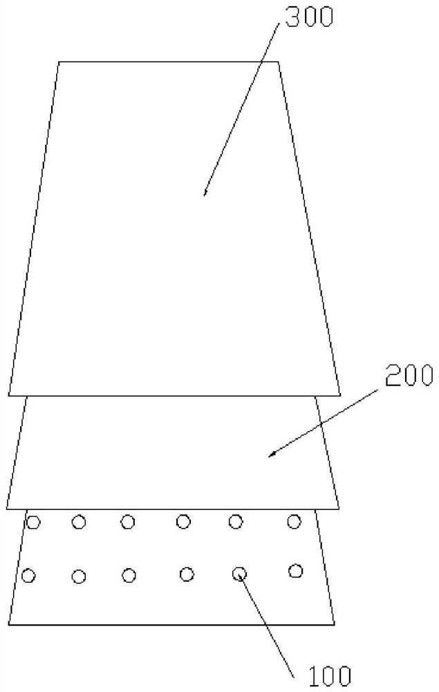
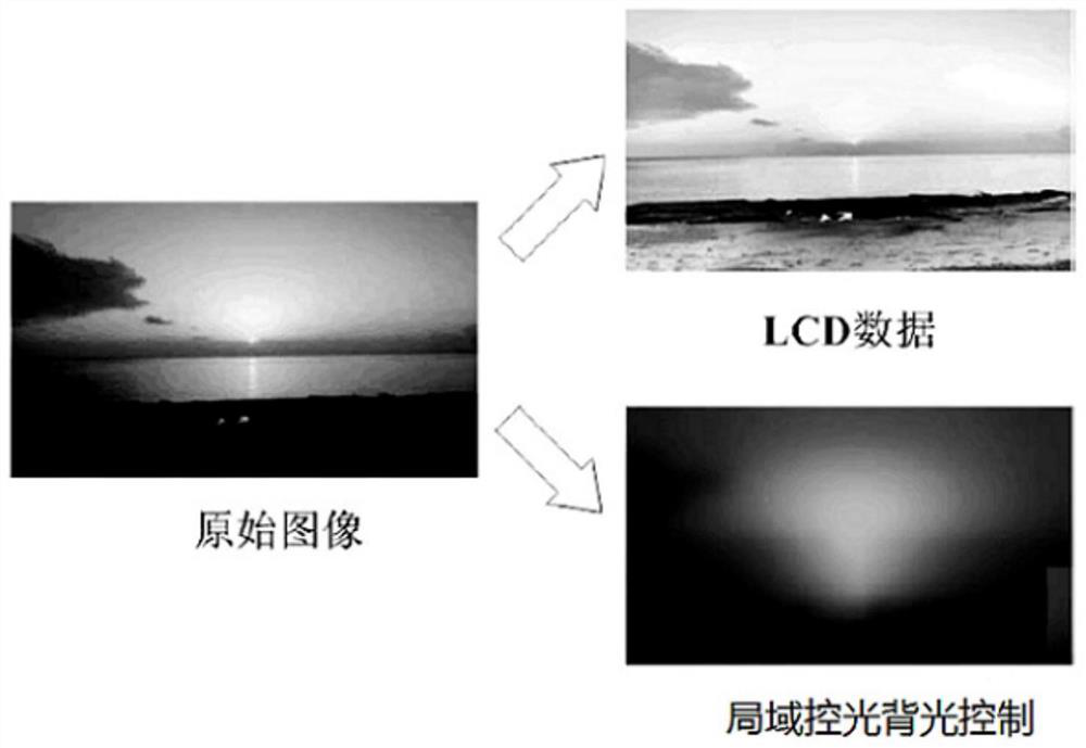
Technical field [0001] The present invention relates to the field of liquid crystal display, and more particularly to a backlight module, a display device, and a control method thereof. Background technique [0002] TFT-LCD (thin film transistor liquid crystal display) is one of a majority of liquid crystal displays, and TFT-LCD has no way to reach an absolute closing state, so its static contrast is technically bottleneck compared to OLED (static contrast is generally upper limit ≤ 6000: 1 ), The contrast of 10,000: 1 or even 400000: 1 required by HDR is unable to reach. At present, there is a technical means for the local area control light (LOCAL DIMMING) technique to reduce dark light, lifting contrast, such display devices are mostly straight backlight, structure figure 1 As shown, from the bottom to the upper, respectively, a plurality of LED chips 100, optical film 200, and TFT-LCD display 300, optical film sheet 200, and TFT-LCD display 300, and the working principle, re...

Claims


Application Information

Patent Timeline
Patent Type & Authority Applications(China)
IPC IPC(8): G02F1/13357G02F1/1334G02F1/1343
CPCG02F1/133603G02F1/1334G02F1/134309
Inventor 历志辉
Owner HUIZHOU VISION NEW TECH CO LTD
Learn More