Eureka AIR delivers breakthrough ideas for toughest innovation challenges, trusted by R&D personnel around the world.

Wire rod girdling automation equipment

A technology for automation equipment and wire loops, which is applied to equipment for dismantling/armoring cables, cable installation devices, electrical components, etc., which can solve the problems that the surface of the wire cannot be re-injected, and the injection layer falls off, so as to facilitate production control, Improve efficiency and yield and save manpower

Pending Publication Date: 2021-03-05
SUZHOU LINGYU ELECTRONICS TECH CO LTD
View PDF0 Cites 0 Cited by
  • Summary
  • Abstract
  • Description
  • Claims
  • Application Information

AI Technical Summary

Problems solved by technology

[0003] The existing wire stripping mainly relies on laser ring cutting, but the surface of the wire after laser burning cannot be well processed for secondary injection molding
And it is easy to cause the injection layer to fall off

Method used


Image

  • Wire rod girdling automation equipment
  • Wire rod girdling automation equipment
  • Wire rod girdling automation equipment

Examples


Embodiment Construction

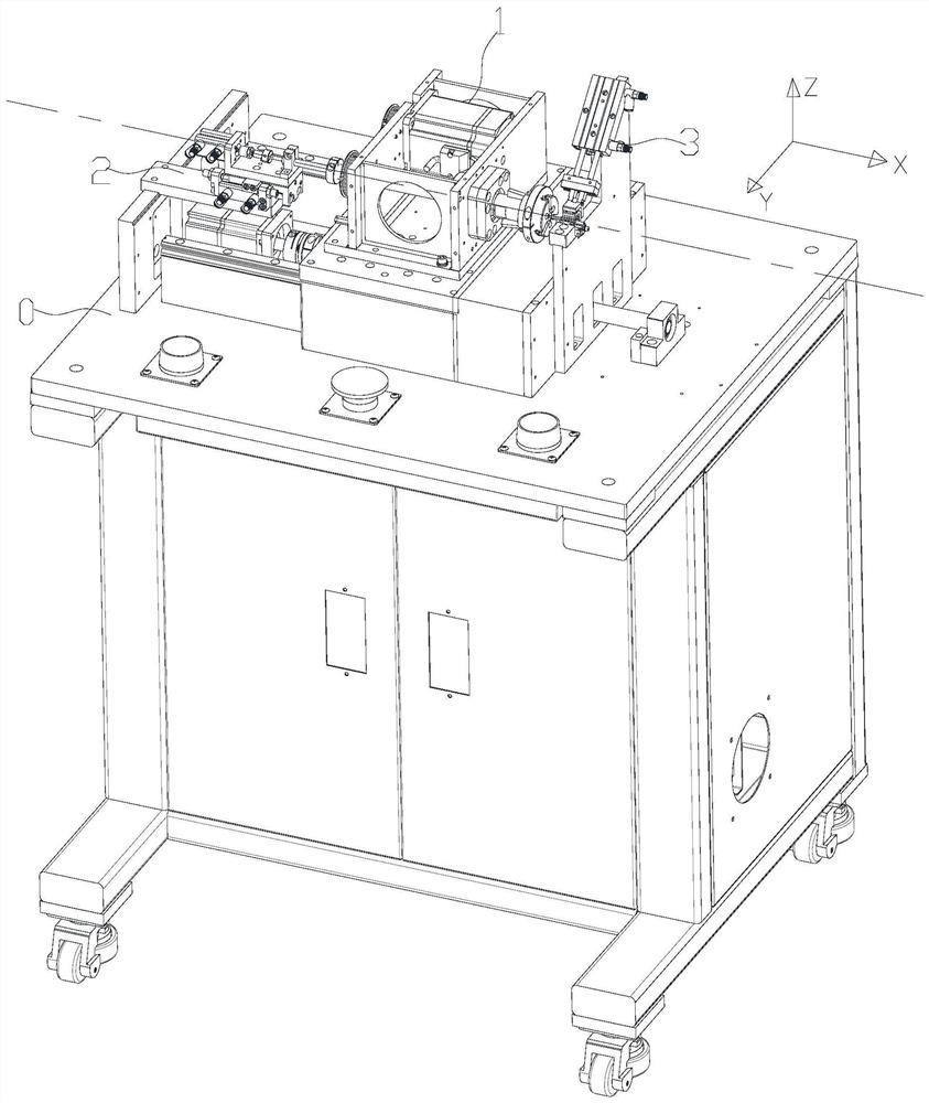
[0035] The present invention will be described in further detail below in conjunction with the accompanying drawings. In this description, the positive direction of the X-axis is the right, the negative direction of the X-axis is the left; the positive direction of the Y-axis is the front, and the negative direction of the Y-axis is the back; the positive direction of the Z-axis is The negative direction of the axis is down.

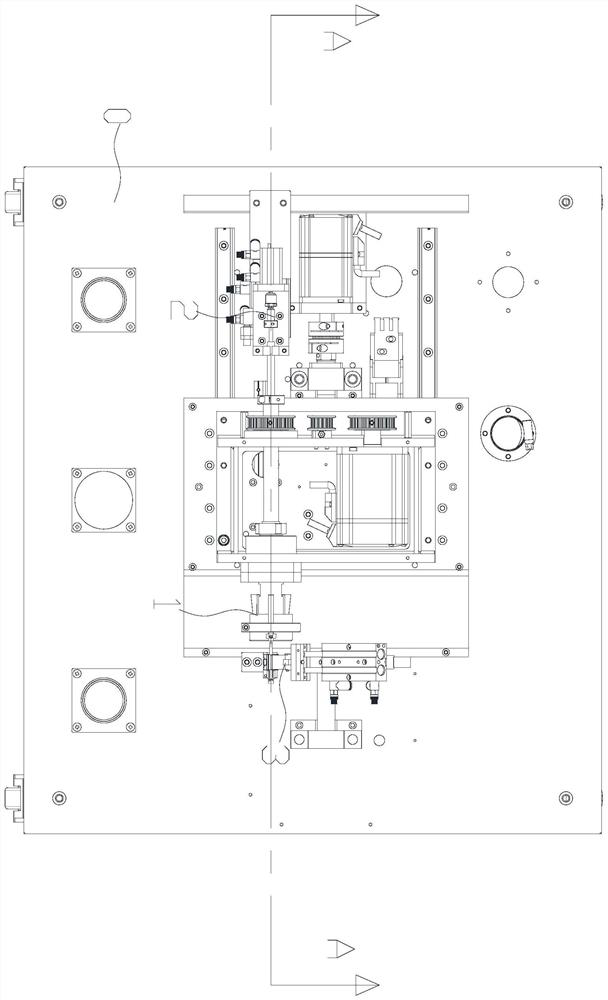
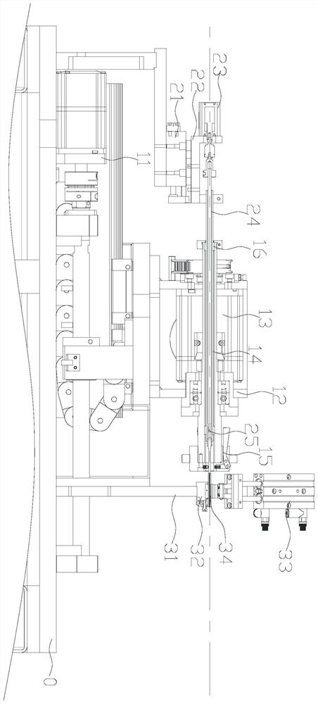
[0036] Figure 1-3 Schematically shows an automatic wire cutting device according to an embodiment of the present invention, including a machine 0, a ring cutting device 1, a first fixing device 2, a second fixing device 3, a ring cutting device 1, a first fixing device The device 2 and the second fixing device 3 are both arranged on the machine table 0, the first fixing device 2 and the second fixing device 3 are respectively located at the left and right ends of the circumcision device 1, and the active end of the first fixing device 2 extends into th...


PUM


Abstract

The invention discloses wire rod girdling automation equipment which comprises a machine table, a girdling device, a first fixing device and a second fixing device. The girdling device, the first fixing device and the second fixing device are arranged on the machine table, and the first fixing device and the second fixing device are located at the two ends of the girdling device respectively. Theacting end of the first fixing device extends into the working end of the girdling device, and the acting ends of the girdling device, the first fixing device and the second fixing device are locatedon the same straight line. The equipment is mainly composed of a girdling device, a first fixing device and a second fixing device. In the working process of the equipment, a wire rod is inserted intothe girdling device, one end of the wire rod enters the first fixing device, the other end of the wire rod is matched with the second fixing device, and the first fixing device works and fixes one end of the wire rod; the second fixing device works to fix the other end of the wire rod, and the ring cutting device works to conduct ring cutting on the wire rod, so that the whole ring cutting treatment on the wire rod is completed.

Description

technical field [0001] The invention relates to the technical field of automatic production equipment, in particular to automatic equipment for circular cutting of wire rods. Background technique [0002] The flexible wire needs to be injected twice in the mold to complete the silicone layer on the surface. The existing technology mainly relies on manual processing, and the production rhythm is slow. The existing automatic wire stripping mainly uses a laser machine to burn the wire. [0003] The existing wire stripping mainly relies on laser ring cutting, but the surface of the wire after laser burning cannot be well processed for secondary injection molding. And it is easy for the injection molding layer to fall off. Contents of the invention [0004] According to one aspect of the present invention, an automatic wire cutting device is provided, including a machine table, a ring cutting device, a first fixing device, and a second fixing device, and the ring cutting dev...

Claims


Application Information

Patent Timeline
Patent Type & Authority Applications(China)
IPC IPC(8): H02G1/12
CPCH02G1/1265
Inventor 朱成诚杨俊
Owner SUZHOU LINGYU ELECTRONICS TECH CO LTD
Why Eureka
Eureka Blog
Learn More