Switching device

A technology of switching device and power switching circuit is applied in the field of circuits to achieve the effects of improving stability, concise structure and improving response speed.

Pending Publication Date: 2021-03-05
HANGZHOU HIKVISION DIGITAL TECH
View PDF0 Cites 2 Cited by
  • Summary
  • Abstract
  • Description
  • Claims
  • Application Information

AI Technical Summary

Problems solved by technology

At present, there is a lack of overcurrent prote

Method used


Image

  • Switching device
  • Switching device
  • Switching device

Examples


Example Embodiment

[0057] In order to make the purpose, technical solutions and advantages of the present application, it will be described in further detail below with reference to the accompanying drawings.

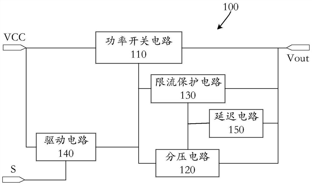
[0058] figure 1 A schematic diagram of a switching apparatus 100 according to some embodiments of the present application is shown. Here, the switching device 100 can be arranged in various electronic devices, and this application does not limit this.

[0059] Such as figure 1 As shown, the switching device 100 can include a power switch circuit 110, a voltage dividing circuit 120, a current limiting protection circuit 130, a drive circuit 140, and a delay circuit 150.

[0060] The power switch circuit 110 is between the power supply terminal VCC and the power supply output VOUT. Here, the power switch circuit 110 powers the power supply output VOUT when turned on, and stops the power supply at disconnection. Power supply output VOUT can be powered to load.

[0061] The voltage divider cir...


PUM


Abstract

The invention discloses a switching device, which comprises a power switch circuit which is located between a power end and a power supply output end, and supplies power to the power supply output endwhen turned on; a voltage division circuit which is used for collecting the voltage drop of the power switch circuit; a current-limiting protection circuit which is used for turning off the power switch circuit when turned on; a drive circuit which turns on the power switch circuit in response to a control signal indicating that the power switch circuit is turned on; a delay circuit which is usedfor preventing the current-limiting protection circuit from being turned on before the power switch circuit is turned on, wherein the voltage division circuit is used for turning on the current-limiting protection circuit when the power switch circuit is in an overcurrent state, so that the current-limiting protection circuit turns off the power switch circuit.

Description

technical field [0001] The present application relates to the field of circuit technology, in particular to switching devices. Background technique [0002] Switching devices are widely used in control circuits of various electronic devices. For over-current protection, switching devices of electronic equipment usually use comparators and digital chips for over-current protection. Here, the method of using comparators and digital chips has the risk of chip control logic getting out of control. At present, there is a lack of an overcurrent protection switch with a simple and stable structure. Contents of the invention [0003] Embodiments of the present application provide a switch device, comprising: [0004] The power switch circuit is located between the power supply terminal and the power supply output terminal, and supplies power to the power supply output terminal when it is turned on; [0005] a voltage divider circuit, collecting the voltage drop of the power sw...

Claims


Application Information

Patent Timeline
IPC IPC(8): H03K17/082H03K17/042H02H9/02H02H3/08
CPCH03K17/042H03K17/082H02H3/08H02H9/02
Inventor 陈冲
Owner HANGZHOU HIKVISION DIGITAL TECH
Why Eureka
Try Eureka