
Filter pressing equipment for producing nano calcium carbonate

A nano-calcium carbonate and equipment technology, applied in the direction of filtration circuit, filtration separation, mobile filter element filter, etc., can solve problems such as laborious and troublesome operation

Inactive Publication Date: 2021-03-09
江西科越科技有限公司
View PDF6 Cites 0 Cited by
  • Summary
  • Abstract
  • Description
  • Claims
  • Application Information

AI Technical Summary

Problems solved by technology

[0004] In order to overcome the disadvantages that people constantly squeeze the nano-calcium carbonate, so that the water is squeezed out, it is more laborious, and people need to constantly move tools to squeeze the nano-calcium carbonate, and the operation is more troublesome. Technical problem: provide a It is a filter press equipment for nano calcium carbonate production that can replace manual extrusion of nano calcium carbonate, which is labor-saving and convenient to operate.

Method used


Image

  • Filter pressing equipment for producing nano calcium carbonate
  • Filter pressing equipment for producing nano calcium carbonate
  • Filter pressing equipment for producing nano calcium carbonate

Examples


Embodiment 1

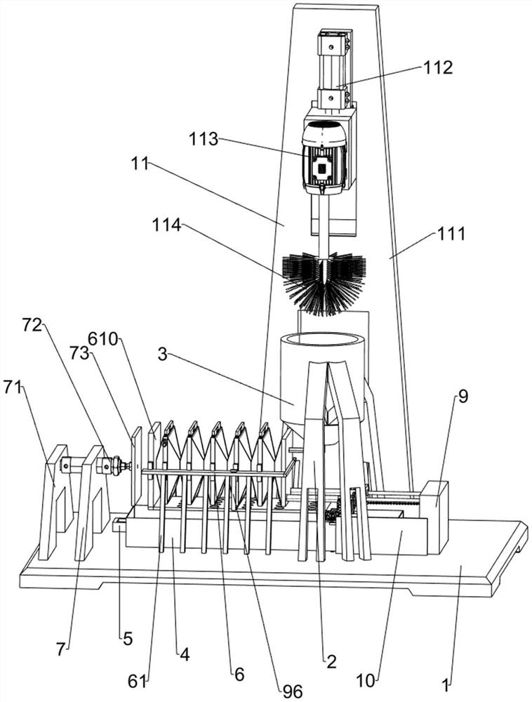
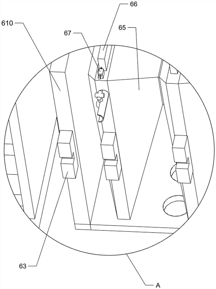
[0026] A kind of pressure filter equipment for the production of nanometer calcium carbonate, such as Figure 1-Figure 4 As shown, it includes a base 1, a first fixing bracket 2, an inlet barrel 3, a liquid storage tank 4, a handle 5, a filter mechanism 6 and an extruding device 7, and four first fixing brackets are fixed in the middle of the top right side of the base 1. Bracket 2, feed cylinder 3 is fixedly connected between the inner ends of the four first fixed brackets 2, a liquid storage tank 4 is placed in the middle of the top of the base 1, a handle 5 is fixedly connected to the middle part of the outer left side of the liquid storage tank 4, and the base 1 A filter mechanism 6 is provided on the top, and the filter mechanism 6 is connected and communicated with the discharge end of the feeding cylinder 3 . The left side of the top of the base 1 is provided with an extruding device 7 , and the extruding device 7 cooperates with the filter mechanism 6 .

[0027] The fi...

Embodiment 2

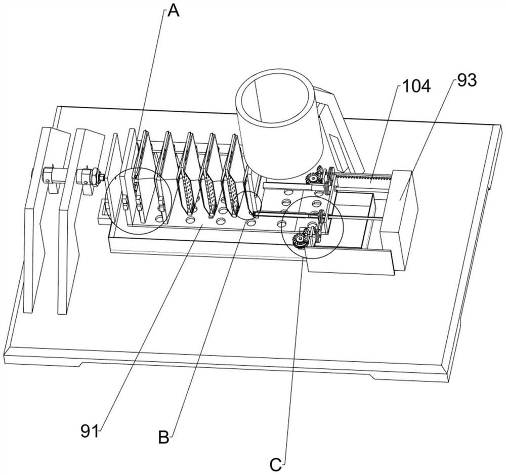
[0033] On the basis of Example 1, such as figure 1 , figure 2 with Figure 5 As shown, a cleaning mechanism 9 is also included, and the cleaning mechanism 9 includes a filter plate 91, a cleaning pipe 92, a fixed block 93, a fixed rod 94, a cleaning block 95 and a scraper 96, and the front and rear sides of the first fixed plate 62 are right A scraper 96 is fixedly connected between the parts, and a sliding cleaning pipe 92 is provided in the discharge pipe 68, and a filter plate 91 is fixedly connected between the outer right of the cleaning pipe 92 on the front and rear sides, and the outer bottom of the scraper 96 is connected to The inner bottom of the filter plate 91 is in contact with each other, the left side of the inner bottom of the filter plate 91 is fixedly connected with the bottom of the extruding plate 73, the middle of the right side of the top of the base 1 is fixed with a fixed block 93, and the upper left side of the fixed block 93 is symmetrically fixed w...

Embodiment 3

[0038] On the basis of embodiment 1 and embodiment 2, such as figure 1 with Figure 6 As shown, a cleaning mechanism 11 is also included. The cleaning mechanism 11 includes a sixth fixed plate 111, a second cylinder 112, a motor 113 and a hair brush 114. Six fixed plates 111 are provided with a sliding motor 113 on the upper front side of the front side, and the output shaft end of the motor 113 is fixedly connected with a hairbrush 114. The second air cylinder 112, the end of the telescopic rod of the second air cylinder 112 is fixedly connected with the top of the motor 113 .

[0039] It also includes a ball valve 12. The ball valve 12 includes a fixed pipe 121, a notched ball 122 and a rotary rod 123. The upper part of the front side of the leftmost second fixed plate 64 is fixedly connected with the fixed pipe 121 and communicated with it. A rotary rod 123 is passed through, and a notched ball 122 is fixedly connected to the bottom end of the rotary rod 123, and the notc...


PUM


Abstract

The invention relates to filter pressing equipment, in particular to filter pressing equipment for producing nano calcium carbonate. The technical problem to be solved is how to design the filter pressing equipment for producing the nano calcium carbonate, which can replace manpower to extrude the nano calcium carbonate, is labor-saving and is convenient to operate. A filter pressing device for nano calcium carbonate production comprises a base, four first fixing supports, four second fixing supports and a filter pressing device, one side of the base is fixedly connected with the four first fixing supports, and the feeding cylinder is fixedly connected among the end parts of the four first fixed brackets far away from the base. A proper amount of nano calcium carbonate is placed in the feeding barrel and falls into the filtering mechanism, the extruding device is started, the extruding device operates to make contact with the filtering mechanism to drive the filtering mechanism to operate, the filtering mechanism operates to extrude out water in the nano calcium carbonate, in this way, the nano calcium carbonate does not need to be manually extruded by people, labor is saved, and convenience is achieved.

Description

technical field [0001] The invention relates to a filter press device, in particular to a filter press device for producing nanometer calcium carbonate. Background technique [0002] In the production process of nano-calcium carbonate, nano-calcium carbonate will be mixed with water, and the water in nano-calcium carbonate needs to be squeezed out before using nano-calcium carbonate. At present, most of them are processed by people. Nano-calcium carbonate is extruded so that water is extruded. After a long time, it is more laborious, and people need to constantly move tools to extrude nano-calcium carbonate, which is troublesome to operate. [0003] Therefore, it is necessary to design and develop a filter press equipment for nano-calcium carbonate production that can replace manual extrusion of nano-calcium carbonate, which is labor-saving and convenient to operate. Contents of the invention [0004] In order to overcome the disadvantages that people constantly squeeze t...

Claims


Application Information

Patent Timeline
Patent Type & Authority Applications(China)
IPC IPC(8): B01D61/00B01D65/04B01D33/01B01D33/46B01D36/02
CPCB01D61/00B01D65/027B01D33/015B01D33/466B01D36/02B01D2321/30
Inventor 陈建平宁连香
Owner 江西科越科技有限公司
Learn More