a cleaning tool

A cleaning tool and cleaning department technology, applied in cleaning equipment, cleaning machinery, carpet cleaning, etc., can solve the problems of complicated operation of peripheral pedals, insufficient squeezing, laborious squeezing, etc., to achieve optimized user experience and smooth squeezing , Ease of use

Active Publication Date: 2022-05-27
永康市清唯工贸有限公司
View PDF8 Cites 0 Cited by
  • Summary
  • Abstract
  • Description
  • Claims
  • Application Information

AI Technical Summary

Problems solved by technology

[0005] The technical problem to be solved by the present invention is to provide a mop-squeezable dehydrating cleaning device for the defects in the prior art that when the mop is squeezed dry, the squeeze is not sufficient, the squeeze is laborious, and peripheral pedals are required to cooperate with footsteps to operate complicatedly. tool

Method used


Image

  • a cleaning tool
  • a cleaning tool
  • a cleaning tool

Examples


Embodiment 1

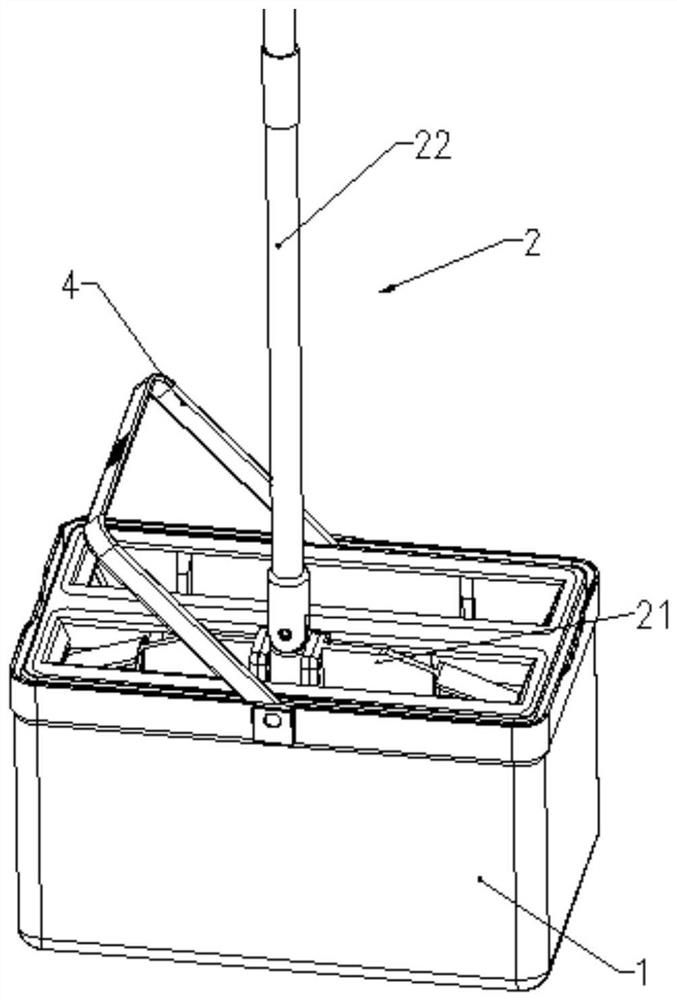
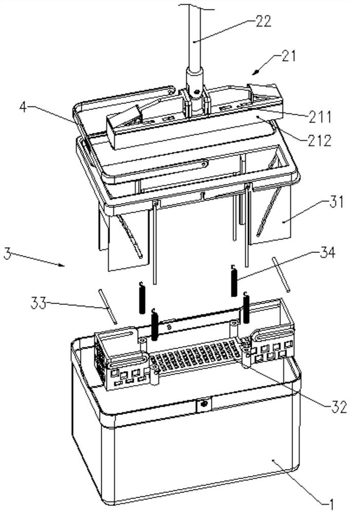
[0067] see Figures 1 to 8 As shown, this embodiment provides a cleaning tool that can squeeze a mop for dehydration, including a mop, the mop includes a mop bar 22 and a mop head 21 connected to the mop bar 22, the mop head 21 includes a mop plate 211, and a mop mounted on the mop The cleaning part 212 on the plate, the cleaning part 212 can be deformed after dehydration. The cleaning part 212 can be made of materials such as some materials that expand after absorbing water, shrink after dehydration, and can be deformed to different degrees, such as foamed cotton tips, colloidal cotton tips, sponge tips, or the like.

[0068] The mop board 211 is generally in the shape of a strip or plate, and has a longer length direction and a shorter width direction. The mop bar 22 and the mop head 21 are rotatably connected. The mop rod 22 can be rotated relative to the mop head 21 in a plane perpendicular to the length direction of the mop plate 211, and the rotation range is 0-180°. I...

Embodiment 2

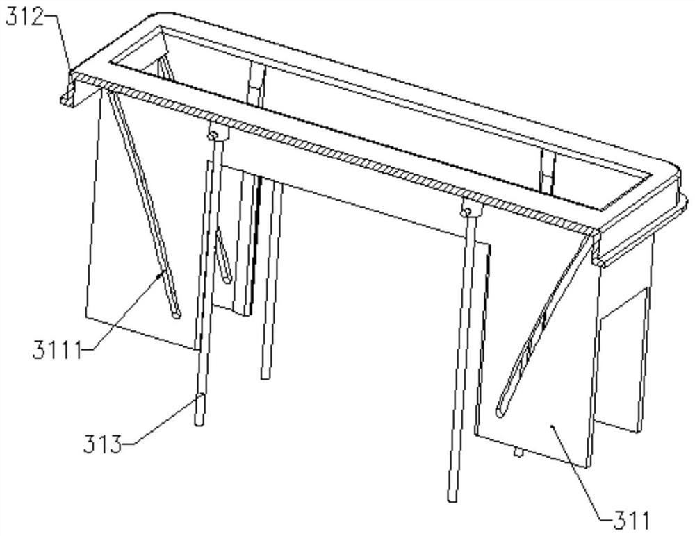
[0099] The difference between this embodiment and Embodiment 1 is as follows: the guide portion 2111 is a guide groove 2111b formed at both ends of the mop plate 211, and the mop rod 22 is pressed down, and a pair of extruders 33 symmetrically arranged on both sides of the mop head 21 can be Sliding in the guide groove 2111b, during the sliding process, the collodion is squeezed to dehydrate.

[0100] combine Figure 9 As shown, the upper end of the first movable slot 3111 is located inside the lower end. The length of the mop head 21 is greater than the length of the batt; the guide groove 2111b is located outside the length of the batt. The outer side of the guide groove 2111b is high and the inner side is low. In the initial state, the distance between the upper surface of the pressing plate 321 and the lower end of the pressing member 33 is not less than the distance between the lower end of the rubber cotton and the lower end of the guide groove 2111b, and the upper sur...

Embodiment 3

[0102] The difference between this embodiment and Embodiment 1 is as follows: the guide portion 2111 is a guide rail 2111c formed at both ends of the mop plate 211, and the mop rod 22 is pressed down. The guide rail 2111c slides, and in the process of sliding, the collodion is squeezed to dehydrate.


PUM


Abstract

The invention relates to a cleaning tool that can squeeze a mop for dehydration, comprising: a bucket body; a mop, the mop includes a cleaning part that can be deformed after dehydration; a water squeezing component, the water squeezing component includes: Extruding plate; an extruding member movable relative to the extruding plate, forming a wringing area suitable for extruding the cleaning part between the extruding member and the extruding plate; a transmission mechanism, suitable for The extruding plate and the extruding part are connected by transmission; the transmission mechanism can drive the extruding plate and the extruding part to move simultaneously, and the moving speed of the extruding part in the vertical direction is greater than the set The moving speed of the extruding plate along the vertical direction makes the height of the wringing area decrease, so as to realize the water squeezing of the cleaning part opposite to the wringing area. The moving speed of the extruded parts increases the moving distance, and the extruded mop is more labor-saving and easier.

Description

technical field [0001] The invention belongs to the technical field of cleaning supplies, and relates to a cleaning tool for dehydrating a hand-pressed mop, especially for some mops that use foamed cotton tips, colloidal cotton tips, sponge tips or the like as mop heads. In the selection of materials, porous materials with good water absorption are mostly used, which can be made of wood cellulose fibers or foamed plastic polymers. When these materials are used as mop heads, they generally have It can swell after absorbing water, shrink after dehydration, and can be deformed to different degrees. Background technique [0002] The collodion mop is a mop that uses collodion to mop the floor. It has the advantages of strong water absorption, high water storage, good toughness, softness, and easy replacement. It is a common household cleaning appliance. [0003] The Chinese invention patent with the document number CN208404441U discloses a rubber cotton flat mopping bucket, incl...

Claims


Application Information

Patent Timeline
Patent Type & Authority Patents(China)
IPC IPC(8): A47L13/257A47L13/59
CPCA47L13/257A47L13/59
Inventor 应勤勇
Owner 永康市清唯工贸有限公司
Why Eureka
Try Eureka