Automatic press-fitting equipment for barometer pointer
A barometer and equipment technology, applied in the direction of metal processing equipment, metal processing, manufacturing tools, etc., can solve the problems of long time consumption, air leakage of threaded pipe, low installation efficiency, etc., achieve high degree of automation, avoid air leakage, and work The effect of improving efficiency
- Summary
- Abstract
- Description
- Claims
- Application Information
AI Technical Summary
Problems solved by technology
Method used
Image
Examples
specific Embodiment approach 1
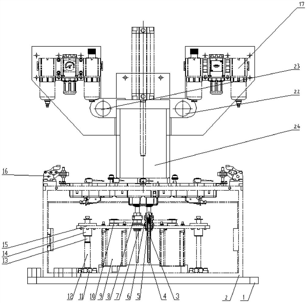
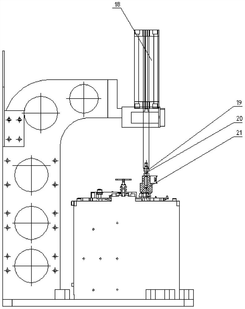
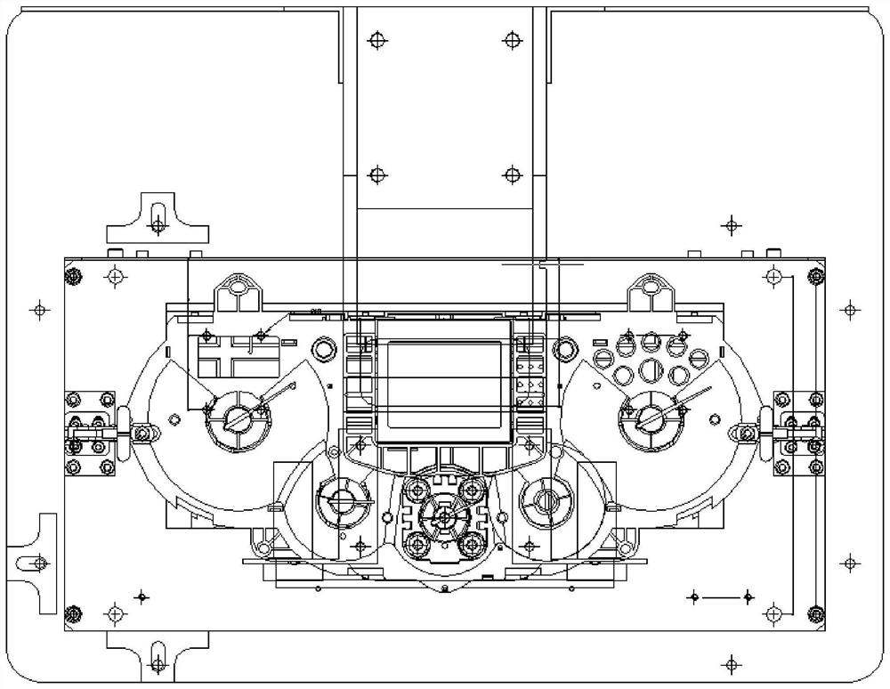
[0024] Specific implementation mode one: refer to Figure 1 to Figure 3 Describe this embodiment. This embodiment provides an automatic press-fitting device for a barometer pointer. , and the upper air mechanism is fixedly connected with the support mechanism, the fixed mechanism is arranged on the support mechanism, and the fixed mechanism is fixedly connected with the support mechanism, the press-fit mechanism is arranged on the support mechanism, and the press-fit mechanism is fixedly connected with the support mechanism, the press-fit mechanism , fixing mechanism, and upper air mechanism are arranged from top to bottom.
[0025] The automatic press-fitting equipment for the pointer of the barometer provided in this embodiment is provided with a support mechanism, an air supply mechanism, a fixing mechanism and a press-fitting mechanism, which realizes the automation of the instrument panel pointer press-fitting process, saves man-hours in the entire pressing process, The ...
specific Embodiment approach 2
[0026] Specific implementation mode two: refer to figure 1 Describe this embodiment. This embodiment is to further limit the support mechanism described in the first specific embodiment. In this embodiment, the support mechanism includes a bottom plate 1, an upper air frame 2 and a pressure head bracket 24. The frame 2 is arranged on the base plate 1, and the upper air frame 2 is fixedly connected with the base plate 1. The indenter bracket 24 is an L-shaped structure, and the indenter bracket 24 is arranged on the rear side of the upper air frame 2. One end of the indenter bracket 24 is connected to the upper air frame 2. The bottom plate 1 is fixedly connected, the other end of the pressure head bracket 24 is arranged directly above the upper air frame 2, the upper air mechanism is arranged in the upper air frame 2, and the upper air mechanism is fixedly connected with the bottom plate 1, and the fixing mechanism is fixed on On the upper surface of the upper air frame 2, the...
specific Embodiment approach 3
[0028] Specific implementation mode three: refer to figure 1 Describe this embodiment. This embodiment is to further limit the upper air mechanism described in the first specific embodiment. In this embodiment, the upper air mechanism includes two upper air devices, a motor pallet and a synchronous platform 15 , two upper air devices, a motor pallet and a synchronous platform 15 are all arranged in the upper air frame 2, the two upper air devices are arranged symmetrically with respect to the center line of the motor pallet length direction, and each upper air device is connected to the bottom plate 1. Fixedly connected, the synchronous platform 15 is arranged on the top of the two upper air devices, and each upper air device is fixedly connected with the synchronous platform 15, and the air outlet of each upper air device is set correspondingly to an air inlet of the barometer. Other compositions and connection methods are the same as those in the second embodiment.
[0029] I...
PUM
 Abstract
Description
Claims
Application Information
 - R&D
- Intellectual Property
- Life Sciences
- Materials
- Tech Scout
- Unparalleled Data Quality
- Higher Quality Content
- 60% Fewer Hallucinations
Browse by: Latest US Patents, China's latest patents, Technical Efficacy Thesaurus, Application Domain, Technology Topic, Popular Technical Reports.
© 2025 PatSnap. All rights reserved.Legal|Privacy policy|Modern Slavery Act Transparency Statement|Sitemap|About US| Contact US: help@patsnap.com


