A high-rigidity lifting device for ultra-precision machining

A technology of ultra-precision machining and lifting devices, which is applied in metal processing equipment, metal processing machinery parts, manufacturing tools, etc., can solve problems such as lack of rigidity, achieve the effect of improving overall rigidity and precision, and ensuring guiding accuracy

Active Publication Date: 2022-05-03
姜堰经济开发区科创中心
View PDF0 Cites 0 Cited by
  • Summary
  • Abstract
  • Description
  • Claims
  • Application Information

AI Technical Summary

Problems solved by technology

[0002] With the continuous development of science and technology, the application of ultra-precision subjects in high-precision industries is becoming more and more extensive. At present, for the field of ultra-precision machining, the existing ultra-precision diamond lathes, ultra-precision multi-axis milling machines, and ultra-precision single-point flying machines are mainly used. Turning machine tools and other equipment, this kind of equipment involves the problem of adjusting the height of the tool tip. The adjustment accuracy of the tool tip height is required to be at the micron level. The lifting device with rigidity has insufficient precision, while the precision with lack of rigidity

Method used


Image

  • A high-rigidity lifting device for ultra-precision machining
  • A high-rigidity lifting device for ultra-precision machining

Examples


Embodiment Construction

[0014] The present invention is described in further detail now in conjunction with accompanying drawing. These drawings are all simplified schematic diagrams, which only illustrate the basic structure of the present invention in a schematic manner, so they only show the configurations related to the present invention.

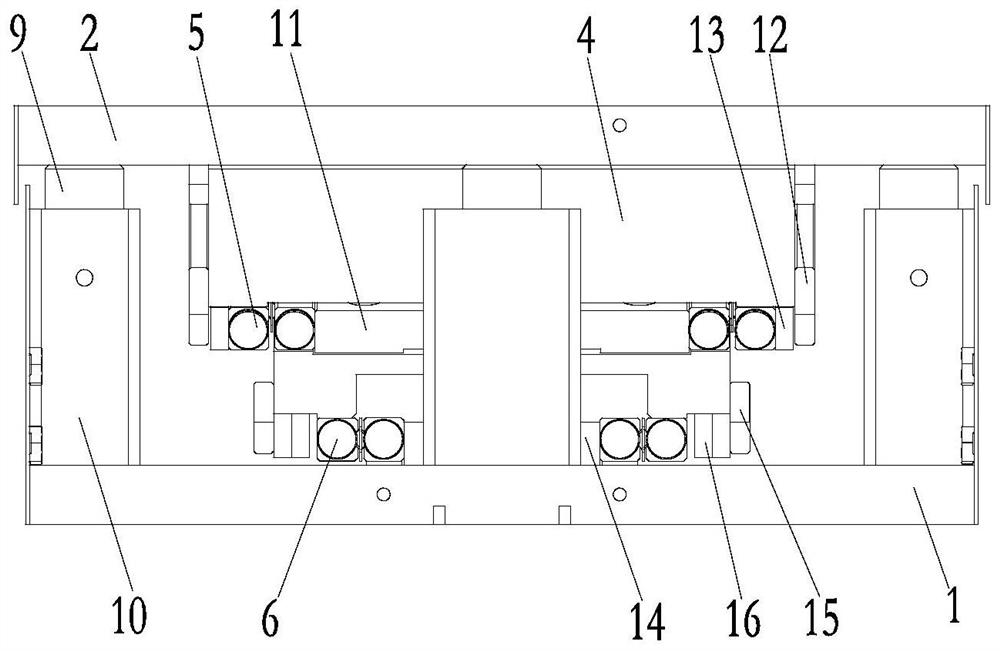
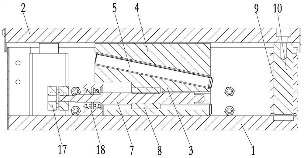
[0015] Such as figure 1 , figure 2 The shown high-rigidity lifting device for ultra-precision machining has a base 1 and a lifting panel 2 above the base 1 . The edge of the base 1 is ring-connected with three guide seats 9 made of brass through bolts, and the bottom surface of the lifting panel 2 is fixed with a lifting guide column 10 through bolts. The guide seat 9 has an upward guiding inner hole, and the guide seat The guide inner hole of 9 and the lifting guide post 10 adopt a tolerance sliding fit, and lubricating oil is added to the contact surface of the two to reduce friction.

[0016] The base 1 is provided with a lower wedge-shaped block 3 faci...


PUM


Abstract

The invention relates to a high-rigidity lifting device for ultra-precision machining, which has a base and a lifting panel. The base is provided with a lower wedge-shaped block with an upward inclined surface, and an upper wedge-shaped block with an inclined surface and the lower wedge-shaped block is fixed on the bottom surface of the lifting panel. The first friction guide rail is fixed on the slope of the upper wedge block, the slope of the lower wedge block is slidingly matched with the first friction guide rail, the second friction guide rail is fixed on the base, the bottom surface of the lower wedge block is slidingly fitted with the second friction guide rail, and the bottom surface of the lower wedge block is slidingly fitted with the second friction guide rail. A trapezoidal lead screw is provided for rotation in the wedge-shaped block, and a trapezoidal nut that is rotatably matched with the trapezoidal lead screw is fixedly connected on the lower wedge-shaped block. The invention realizes the adjustment of the height of the device through the lifting effect of the wedge-shaped motion generated by the translation of the lower wedge-shaped block on the upper wedge-shaped block. Since the sliding friction is used to replace the rolling friction motion used in the traditional lifting device, the overall rigidity and accuracy of the device are improved. , to ensure the guiding accuracy during the lifting process and the anti-vibration effect during the processing.

Description

technical field [0001] The invention relates to the technical field of precision machining, in particular to a high-rigidity lifting device for ultra-precision machining. Background technique [0002] With the continuous development of science and technology, the application of ultra-precision subjects in high-precision industries is becoming more and more extensive. At present, for the field of ultra-precision machining, the existing ultra-precision diamond lathes, ultra-precision multi-axis milling machines, and ultra-precision single-point flying machines are mainly used. Turning machine tools and other equipment, this kind of equipment involves the problem of adjusting the height of the tool tip. The adjustment accuracy of the tool tip height is required to be at the micron level. The lifting device with rigidity has insufficient precision, and the precision with lack of rigidity. Contents of the invention [0003] The technical problem to be solved by the present inv...

Claims


Application Information

Patent Timeline
Patent Type & Authority Patents(China)
IPC IPC(8): B23Q1/25
CPCB23Q1/25
Inventor 谷秋梅
Owner 姜堰经济开发区科创中心
Why Eureka
Try Eureka