Eureka AIR delivers breakthrough ideas for toughest innovation challenges, trusted by R&D personnel around the world.

Convenient-to-disassemble tool fixture for automobile part machining tool

A technology for processing machine tools and auto parts, applied in metal processing machinery parts, manufacturing tools, metal processing equipment, etc., can solve the problems of easily damaged fixtures, excessive clamping force, affecting processing accuracy, etc.

Inactive Publication Date: 2021-03-09
李永刚
View PDF0 Cites 3 Cited by
  • Summary
  • Abstract
  • Description
  • Claims
  • Application Information

AI Technical Summary

Problems solved by technology

[0005] Aiming at the deficiencies of the prior art, the present invention provides a tool holder for an auto parts processing machine tool that is easy to disassemble. It has the advantages of ensuring a suitable clamping force, convenient disassembly, adjustment of the protruding length of the tool, and high machining accuracy. It solves the problem that the existing tool fixture is inconvenient to fix, the clamping force is not enough and it is easy to loose, the clamping force is too large, it is easy to damage the fixture, and it will cause inconvenient disassembly, and the fixed tool cannot be adjusted for the extension length, which affects the machining accuracy. question

Method used


Image

  • Convenient-to-disassemble tool fixture for automobile part machining tool
  • Convenient-to-disassemble tool fixture for automobile part machining tool
  • Convenient-to-disassemble tool fixture for automobile part machining tool

Examples


Embodiment Construction

[0025] The following will clearly and completely describe the technical solutions in the embodiments of the present invention with reference to the accompanying drawings in the embodiments of the present invention. Obviously, the described embodiments are only some, not all, embodiments of the present invention. Based on the embodiments of the present invention, all other embodiments obtained by persons of ordinary skill in the art without making creative efforts belong to the protection scope of the present invention.

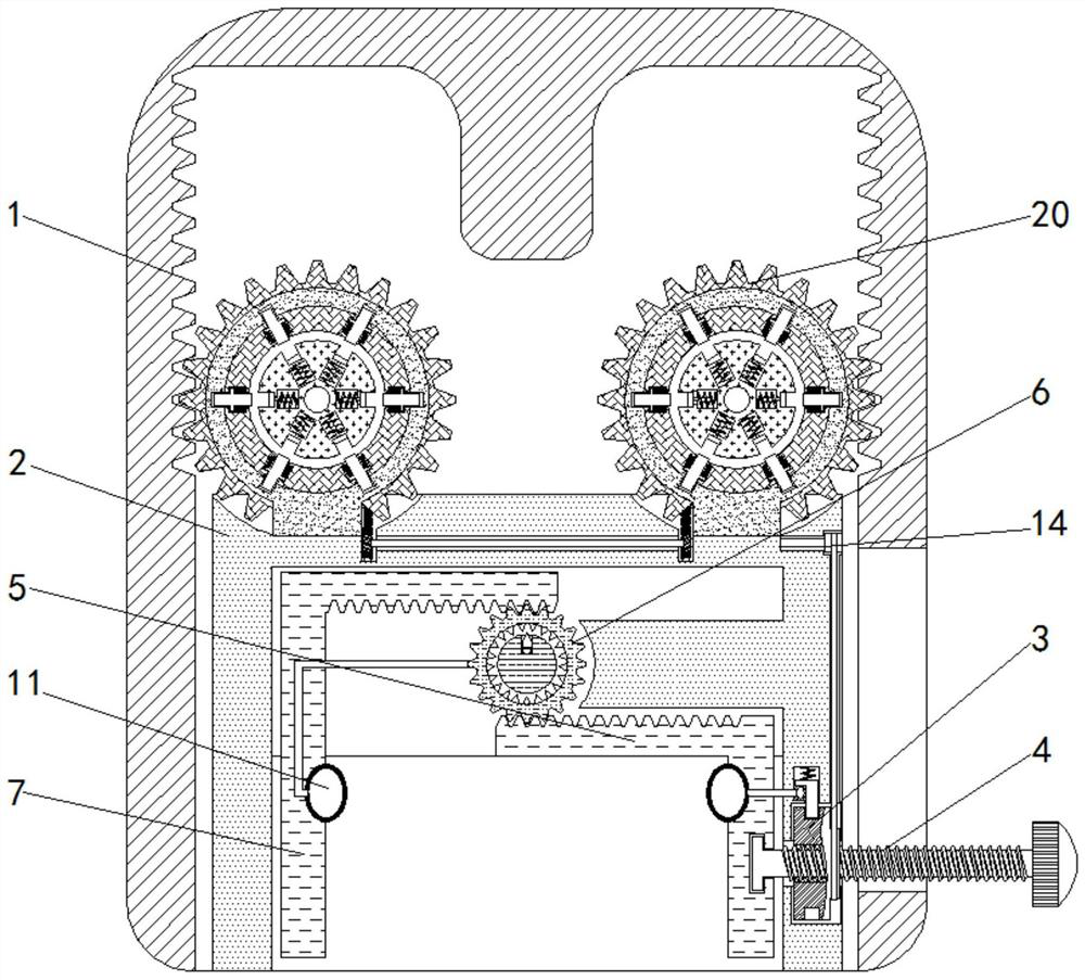
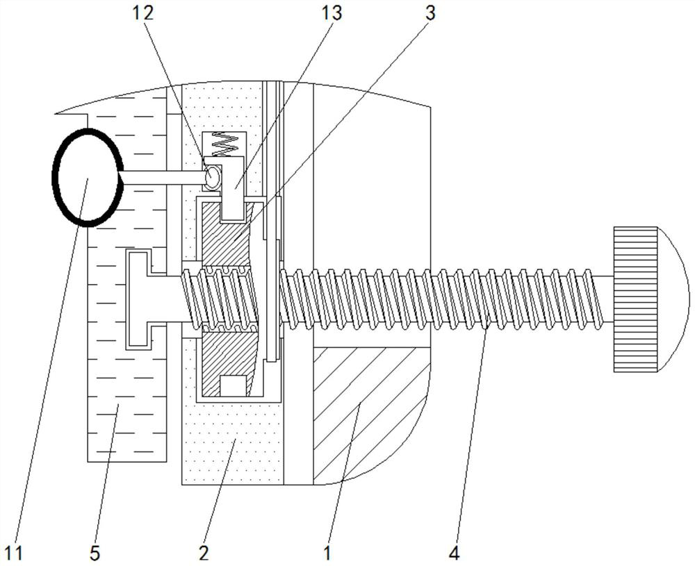
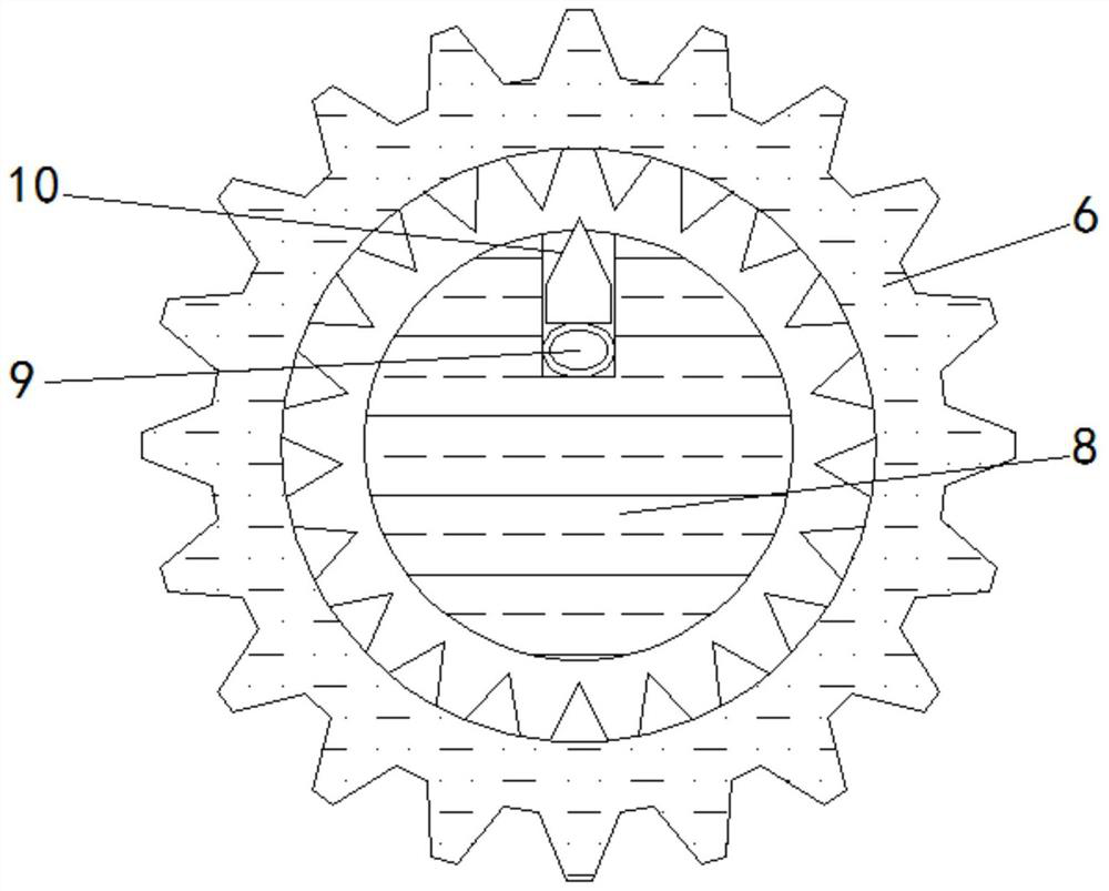
[0026] see Figure 1-5 , a tool holder for an auto parts processing machine tool that is easy to disassemble, including a fixed frame 1, the inner wall of the fixed frame 1 is provided with tooth grooves, used in conjunction with a gear 20, so that the gear 20 can drive the bracket 2 to move when rotating, and the fixed frame 1 The inside of the bracket 2 is slidingly connected with a bracket 2, the inside of the bracket 2 is fixedly connected with an adjustme...


PUM


Abstract

The invention relates to the technical field of automobile part machining, and discloses a convenient-to-disassemble tool fixture for an automobile part machining tool. The tool fixture comprises a fixed frame; a support is connected with the fixed frame in a sliding manner; the interior of the support is fixedly connected with an adjusting wheel; limiting rods are connected with the interior of agear in a sliding manner; the outer side of each limiting rod is fixedly connected with reset springs; and the front face of the gear is fixedly connected with a limiting wheel. According to the convenient-to-disassemble tool fixture for the automobile part machining tool, an adjusting rod is rotated, and moves leftwards under the action of the adjusting whee; the adjusting rod drives a right clamping plate to move leftwards; the right clamping plate drives a driving wheel to rotate; the driving wheel drives a left clamping plate to move rightwards; the right clamping plate and the left clamping plate drive pressure balls to get close to a tool; the tool makes the pressure ball compressed; the pressure balls are compressed to make a push ball to expand; the push ball drives a snap rod toascend; and then the snap rod and the adjusting wheel are used in cooperation, so that the effect of guaranteeing proper clamping force is achieved.

Description

technical field [0001] The invention relates to the technical field of automobile parts processing, in particular to a tool holder for an automobile parts processing machine tool which is easy to disassemble. Background technique [0002] Auto parts processing is the various units that constitute the overall processing of auto parts and products that serve the processing of auto parts. Auto parts processing is inseparable from machine tools. Machine tools refer to machines that manufacture machines, also known as machine tools or machine tools. Generally divided into metal cutting machine tools, forging machine tools and woodworking machine tools. [0003] The machine tool often needs to change the tool during processing. The existing tool fixture is inconvenient to fix. The clamping force is not enough and it is easy to loosen. If the clamping force is too large, it will easily damage the fixture and cause inconvenient disassembly. At the same time, the fixed tool cannot be...

Claims


Application Information

Patent Timeline
IPC IPC(8): B23Q3/154
CPCB23Q3/1543
Inventor 李永刚
Owner 李永刚
Why Eureka
Eureka Blog
Learn More