Automobile chassis noise reduction device

An automobile chassis and noise reduction technology, which is applied to vehicle parts, transportation and packaging, etc., can solve the problems of sound insulation, shock absorption, poor noise reduction effect, lack of protective structure, poor installation and fixability, etc., and achieve overall firmness and stability, disassembly Simple and convenient, the effect of firm installation

Pending Publication Date: 2021-03-09
GUILIN UNIV OF ELECTRONIC TECH
View PDF0 Cites 0 Cited by
  • Summary
  • Abstract
  • Description
  • Claims
  • Application Information

AI Technical Summary

Problems solved by technology

[0005] In order to solve the above-mentioned technical problems, the present invention provides an automobile chassis noise reduction device to solve the problem that the existing automobile chassis noise reduction The noise effect is poor, the whole does not have a superior protective structure, and it is easy to cause damage to the chassis

Method used


Image

  • Automobile chassis noise reduction device
  • Automobile chassis noise reduction device
  • Automobile chassis noise reduction device

Examples


Embodiment 1

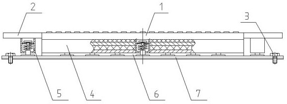
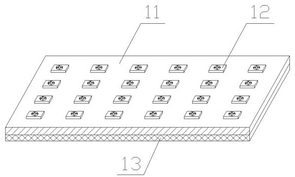
[0028] Embodiment 1: A kind of automobile chassis noise reduction device provided by the present invention comprises a top connecting plate 1, a mounting support plate 2, bolts 3, a noise reduction partition 4, a shock absorbing column 5, a buffer pad 6 and a protective bottom plate 7, wherein : the side of the top connecting plate 1 is integrally welded with a mounting support plate 2, the protective base plate 7 is provided with bolts 3, and the protective base plate 7 is fixedly installed with the automobile chassis through the bolts 3; the noise reduction partition 4 is welded on the top connection The lower part of the plate 1, and the lower part of the noise reduction partition 4 is fixed by a buffer pad 6 by screws, and the lower part of the buffer pad 6 is fixed by a protective bottom plate 7; , and the lower end of the shock-absorbing column 5 is welded and fixed to the upper side of the protective bottom plate 7; the top connecting plate 1 includes a contact plate 11,...

Embodiment 2

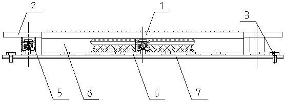
[0031] Embodiment 2: The difference between embodiment 2 and embodiment 1 is that the noise reduction partition 4 in embodiment 1 is replaced by a vacuum sound insulation board 8. In addition to the sound insulation layer 43, the vacuum sound insulation board 8 is also provided with an airtight A cavity 81, and the cavity is in a vacuum state; a check valve 82 is provided outside the vacuum sound insulation board 8, and the check valve 82 communicates with the cavity 81, and the check valve 82 is connected with external vacuum equipment. As we all know, since the sound cannot be retransmitted in a vacuum, the vacuum sound insulation panel 8 can more effectively isolate the chassis noise, and the shock-absorbing column 5 can not only reduce the noise generated by bumps, but also slow down the intensity of sound waves. effect.


PUM


Abstract

The invention provides an automobile chassis noise reduction device. The device comprises a top connecting plate, a mounting supporting plate, bolts, a noise reduction partition plate, damping columns, a buffer pad and a protective bottom plate, the mounting supporting plate is welded to the side face of the top connecting plate, and the protective bottom plate and an automobile chassis are fixedly mounted through the bolts; and the noise reduction partition plate is welded to the lower portion of the top connecting plate, the lower side portion of the noise reduction partition plate is fixedto the upper ends of the damping columns through the bolts, the lower ends of the damping columns are fixed to the side upper portion of the protective bottom plate, and the protective bottom plate isfixed to the lower portion of the buffer pad through screws. Through the arrangement of the top connecting plate, the mounting supporting plate, the noise reduction partition plate, the damping columns, the protective bottom plate and other structures, the mounting firmness of the whole body and the chassis is improved, the overall sound insulation, damping and noise reduction effects are excellent, noise generated by driving is reduced to the maximum extent, an excellent protective structure is achieved, and the use requirement is met.

Description

technical field [0001] The invention belongs to the technical field of auto parts, in particular to an auto chassis noise reduction device. Background technique [0002] Cars are the most common way for modern people to travel. The invention of cars has brought us the convenience of transportation. The car chassis is composed of four parts: transmission system, driving system, steering system and braking system. The function of the chassis is to support and install the automobile engine and its various components and assemblies to form the overall shape of the automobile, and receive the power of the engine to make the automobile move and ensure normal driving. [0003] However, the existing automobile chassis noise reduction device has poor installation fixity between the overall structure and the automobile chassis, and the small mutual friction leads to the phenomenon that the installation is not firm and easy to shake and fall, and the overall sound insulation, shock ab...

Claims


Application Information

Patent Timeline
IPC IPC(8): B60R13/08
CPCB60R13/0861
Inventor 唐荣江张志远郑伟光何水龙许恩永陆增俊
Owner GUILIN UNIV OF ELECTRONIC TECH
Why Eureka
Try Eureka